Ejector Pin

The bigger freedom between the ejector pin and the ejector through-opening not just serves to wipe out the sliding rubbing between the pin and the plate, yet in addition gives required slop to permit to misa lignment between the tomahawks of the ejector openings in different plates. The predetermined freedom ought to surpass the absolute stack-up of the openings’ positional resiliences over the form plates. Since ordinary boring resiliences are on the request for 0.25 mm, a diametral leeway of 0.5 mm should be adequate in most shape making applications. Moreover, a liberal chamfer should be given at the interface between the center addition and the help plate. As shown in china high-precision mould suppliers, this chamfer helps the controlling of the ejector pin from the help plate into the center addition during mold get together.

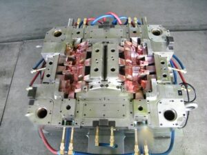
The definite plan of the ejector retainer plate is appeared in injection moulding services china. As appeared in Detail D, a counterbore is given in the ejector retainer plate to pull the top of the ejector pin(s) away from the splitting plane of the shape when the ejector framework is being withdrawn. To give leeway to misalignment of the places of the ejector openings, the counterbore is given a liberal resilience so the centerline of every ejector pin is represented by the mating of the pin with the reamed ejector opening in the center supplements. In the event that a shaped pin is utilized, the top of the pin is normally given a level as appeared in Detail E. An equal space and finding dowel are given in the ejector retainer plate to keep up the right direction of the formed ejector pin.

At whatever point conceivable, the shape architect ought to indicate a similar length and width of ejector pins to encourage form gathering and upkeep. On the off chance that distinctive ejector pins are utilized in the form plan, the shape fashioner and shape creator should make certain to key and name every ejector pin and coordinating area on the ejector retainer plate so the shape can be promptly kept up by the disintegrate. The form fashioner ought to consistently try not to plan ejector sticks that fluctuate just somewhat in their plan, since comparable pins may incidentally be viewed as exchangeable by the disintegrate.


The erroneous gathering of ejector pins may make harm the pins just as the restricting mold hole surfaces.

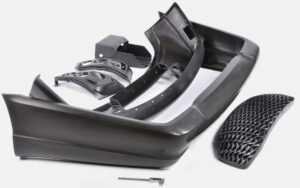
Ejector pins are normally hot manufactured and rotundly ground from hard prepares, (for example, H 13). Stubsequently, the pins are nitrided and cleaned to give an exceptionally hard and smooth surface for low wear and rubbing. Ejector pins are accessible from a few providers in standard measurements (going from 1 mm to 25 mm) and lengths (from 150 1mm to 500 mm). Ordinarily, form creators cut and pound standard ejector pins to the completed length and shape indicated in the shape plan. Be that as it may, ejector pins might be exclusively requested with changing alternatives including distinctive mate rials or surface treatuments, exact diarneters or lengths, strings for mating with the ejector plate, pads, grooves, and so forth While ejector pins are accessible in a scope of breadths and lengths, particularly long pins with little distances across should be dodged, The explanation is that such thin pins will in general clasp under burden. As appeared in plastic injection moulded components china, the stacking of an ejector pin relates to a section with the top end upheld by the drag of the ejector opening, and the base end stuck by the ejector retainer plate. On the off chance that the compressive burden become too huge, at that point the pin may bow or lock an obscure way.

This article is from http://www.chinainjectionmold.com/

Ejection Push Part

When the launch powers on the embellishment have been assessed, the following stage is to decide the total”push territory” of the ejectors onto the shaped part. In particular, there is a base push territory that is needed to maintain a strategic distance from inordinate compressive weight on the discharge system segments just as unnecessary shear weight on the plastic moldings. These two marvels are represented by china mould design services for a solitary pin shooting a bit of the PC bezel.

At the point when the pin is activated with the discharge framework, a response power, Fpin, will create between the pin and the shaped part before the part is shot out. The greatness of this power is identified with the all out discharge power needed to launch the part just as the number, area, and math of the ejectors. The compressive stres on the pin, Opin, is the power on the pin isolated by the region of the pin, or: σpin=Fpin/Aacompession

To stay away from exhaustion or potentially clasping of the launch framework segments, compressive feelings of anxiety must be kept up under a basic edge. This basic pressure, 0 fatigue_ limit is needy upon the material and treatment of the ejectors. Most ejector pins and sleeves are made of solidified materials, with exhaustion limit weights on the request for 800 MPa. A traditionalist shape plan, notwithstanding, may expect a lower weariness limit pressure of 450 MPa for P20. In one or the other case, the all out push territory, all things considered, Aejectors, to keep away from over the top compressive anxieties must meet the necessity.

The necessary push territory to evade abundance compressive anxieties in the discharge framework is exceptionally little in most trim applications invigorated the moderately high of steel. High-precision molds made in china know that the compressive quality of the pins is accordingly not compelling the plan.

Be that as it may, the ejector framework should likewise have enough push zone to try not to create exorbitant shear stresses in the shaped parts upon discharge. For oem/odm industrial injection moulding design factory, the shear pressure applied on the formed part is the power on the pin separated by the territory of the shaped part straightforwardly over the boundary of the pin, or: :

where Qnin is the border of the pin. In the event that the shear pressure in the shaped part is too high, at that point the part can for all time mutilate close to the pin (an impact known as”push pin”), forever twist, or even crack. To dodge these deformities, the form should be planned with the end goal that the edge around all the ejectors gives a shear pressure short of what one-a large portion of the yield pressure of the material, Oplastic veld. This prerequisite prompts the accompanying relationship for the all out border of the ejector framework.

The examination and models show that for most trim applications, the plan of the ejector framework is driven more by the yield stresses applied on the plastic embellishment as opposed to by the compressive weights on the pin. Notwithstanding, compressive pressure can cause locking in long, thin individuals, for example, ejector pins. Consequently, further investigation of the compressive anxieties is significant, and will be accordingly used to dodge pin clasping. This article is from http://www.chinainjectionmold.com

Warpage in Mold Design

There are a few basic systems that ought to be utilized in china mould manufacturing to stay away from and address warpage issues. By a wide margin, the main methodology is to plan a form that will give uniform dissolve temperatures and weights all through the cavity, so the shrinkage of the shaped part(s) will be exceptionally uniform. To augment the shrinkage consistency in close resistance shaping applications, the mold planner of china industrial injection moulding manufacturers should:

■Avoid high stream length to divider thickness proportions by using various entryways;

■Maintain uniform hole pressures by planning a decent feed framework with low stream opposition;

■Maximize the shape surface temperature consistency with a tight cooling line pitch and exceptionally conductive form embeds where required; and

■Facilitate dissolve weight and temperature consistency in the embellishment by requiring uniform part thic kness and liberal filets.

On the off chance that the shape is very much planned, at that point warpage is less inclined to happen. If warpage is experienced, a disintegrate may attempt to lessen or wipe out the warpage by:

■Filling the form depression as quick as conceivable to diminish cooling in the cemented skin;

■Increasing the pack time until the part weight does not increment anymore;

■Increasing the pressing strain to lessen the measure of material shrinkage;

■Utilizing a pack pressure profiling as examined concerning Fig. 10.12 to build dissolve weight and shrinkage consistency over the part;

■Utilizing diverse coolant temperatures on various sides of the form or in various bits of the shape to intentionally control the temperature and shrinkage dissemination; and

■Trying various sorts of materials and filler frameworks with shifting shrinkage practices to discover good execution; a high stream evaluation of polystyrene, (for example, HIPS) can demonstrate if the warpage issue is because of a temperature or weight inclination.

Indeed, even with the all these mold plan and embellishment activities of precision plastic injection mould factory, warpage issues may require shape configuration changes. There are a few shape configuration changes that are usually used to decrease the extent of the warpage, The most widely recognized methodology may be the expansion of at least one doors to improve the consistency of the shrinkage over the pit. Another basic way to deal with decrease the probability of clasping is to expand the sifness of the embellishment through the expansion of shallow ribs. The utilization of Kentucky windage, in spite of the fact that of expanding interest, is more uncommon since it puts a huge weight on the shape creator and form producer, while requiring an exceptionally significant level of prescient capacity and extremely fine surface macintosh hining. Since the dimensional movements of the part diue to warpage may surpass steel safe cutoff points, blunders in this methodology can bring about significant expenses.

The investigation of shrinkage is valuable for determining the shape measurements. Notwithstanding, the shrinkage of the plastic onto the form core(s) additionally decides the powers needed to discharge the shaped part. The assessment of these discharge powers will control the plan of the ejection system in order to try not to misshape the shaped part(s) upon launch. After the launch framework is planned, the form’s basic frameworks in china mould produce services factory are broke down and planned.

This article is from http://www.chinainjectionmold.com

Shrinkage Range

Before making any last suggestions, it is helpful for injection mold company china to survey the likely mistake on the shrinkage gauge. The main blunders in the shrinkage expectations will probably come from the accepted soften weights and temperatures. Consequently, it is valuable to appraise the most extraordinary yet reasonable cutoff points for the weight and temperature to give a lower and maximum cutoff for the shrinkage:

■The lower limit for shrinkage will relate to a pressing stage with a long term and high dissolve pressure. The most extreme term relates to the time at which the plastic soften stops to stream once it Cools to the no stream temperature.

The gauge for the most noteworthy pressing weight is hard to anticipate, since it is represented by the decay’s cycle settings, particulars of the embellishment machine, and so forth A useful maximum breaking point for the pressing weight might be the more noteworthy of 120 % of the infusion weight or 100 MPa.

■The maximum cutoff for shrinkage will relate to a pressing stage with a brief span and low dissolve pressures. The decreased length will make the weight in the cavity completely rot before the plastic dissolve has adequately cooled, along these lines causing unreasonable volumetric shrinkage. Thusly, the most extreme shrinkage might be assessed by assessing the volumetric shrinkage at a low pressing weight (equivalent to the lesser of 40% of the infusion weight or 30 MPa) and a high dissolve temperature (equivalent, maybe, to the temperature somewhere between the no-stream temperature and the liquefy temperature).

Gauge the base and greatest shrinkage for the PC bezel in oem/odm medical injection moulding design factory. To ascertain the base shrinkage, expect that the dissolve temperature and weight toward the finish of pressing are 132°C and 100 MPa, individually. The particular volume toward the finish of packingis 9.50 .10-4 kg/m3, which brings about an expansion in the general volumetric shrinkage to 1.007. The straight shrinkage is assessed to be – 0.2 %. As such, so much material has been stuffed into the hole that the material will extend as opposed to contract once the part is launched out from the form! While this is a fascinating finding and happens infrequently, molds are not typically planned or worked with the aim of acquiring zero or negative shrinkage. The explanation is that some shrinkage is attractive so the plastic trim will pull away from the dividers of the depression and onto the center so the embellishment can be shot out. Negative shrinkage compares to”over packing”of the plastic in the shape depression. In an over pack circumstance, the material remaining parts compacted after shape opening, with the end goal that it may not be conceivable to deliver the part from hole subtleties, for example, ribs and managers.

To figure the most extreme shrinkage, china industrial injection mold suppliers accept that the dissolve temperature and weight toward the finish of pressing are 185°C and 30 MPa, individually. The particular volume toward the finish of pressing is 10.14. 10-3 kg/m3, which brings about a reduction in the general volumetric shrinkage to 0.943. The direct shrinkage is assessed from Eq.10.13 to be 1.9%, which is essentially higher than the recently assessed shrinkage of 0.3%. For this situation, the pressing stage has given lacking material to remunerate to the volumetric shrinkage in the shape hole. The mold designer from high precision plastic injection mould manufacturers ought to propose an all-encompassing pressing stage with higher pressing weights to maintain a strategic distance from abundance shrinkage. This article is from http://www.chinainjectionmold.com/


Shrinkage

The point labeled”shrinking” relates to the second when the shaped polymer arrives at climatic weight. As of now, the polymer may start to contract, pull away from the form dividers, and create elastic burdens. The subsequent point, labeled”ejected,” compares to the second when the shape opens and the part is going to be catapulted. Upon launch, any created tractable anxieties may make the formed part unexpectedly shrivel. The formed part will at that point go through additional unconstrained shrinkage until equilibration and end-use, set apart as the point labeled”end use.” These volumetric shrinkage esteems can be utilized to assess the shaped part shrinkage. For the embellishment cycle plotted in plastic injection factory, the particular volume toward the beginning of shrinkage, discharge, and end-use are 1.116, 1.101, and 1.074 cc/g, separately. From these particular volumes, the anticipated in-form, post-trim, and all out shrinkage are, individually, 0.479%, 0.812%, and 1.291%.

Shrinkage in the thickness course was estimated in injection mold services china with a micrometer including a grasp wheel; a check dependability and repeatability study (check R and R, [10]) was performed with the standard deviation of the estimation being 2.9 um. The right-most section of china high-precision mould suppliers gives the assessed and noticed shrinkage results for each run of the DOE. Expansions in barrel and form coolant temperature brought about higher paces of anticipated shrinkage as (the mean shrinkage is 1.05 % for runs 1 to9 and 1.19% for runs 10to 18 at higher temperature). Expansions in pack pressure brought about lower anticipated shrinkage rates (the mean shrinkage is 1.21% for runs 1-3 and 10-12 at low pack pressure while of 0.95% for runs 7-9 and 16-18 at high pack pressure). The anticipated and noticed shrinkage had a Co-proficient of assurance, R, equivalent to 0.922. While there is some dissipate, the anticipated shrinkage is a sensible assessor for the noticed shrinkage.

Table 10.1 additionally breaks out the anticipated in shape and post form shrinkage dependent on the examination with the noticed weights and temperatures. It is intriguing that the size of the in – form and post – shape shrinkage are each huge supporters of the complete shrinkage, and that a significant part of the noticed conduct follows desires. For instance, the best anticipated post shape shrinkage compares to runs 10 to 12 that gave the least pack pressure and most elevated temperatures, which relates to the most volumetric shrinkage over the DOE runs. Reaction surface investigation was directed to fit a quadratic capacity to the information, with the dissolve pressure being the main determinant of shrinkage.

Contrasted with shrinkage assessment dependent on material provider direction, the trial examination measures the conduct of the shrinkage as a component of dissolve temperature and weight. The shrinkage examination would thus be able to be utilized by injection mould manufacturers in china for form plan in situations where the material properties and cycle conditions are known. The essential wellspring of change is anisotropic shrinkage identified with mathematical requirements inside the form during cooling. In particular, the ductile (canine bone) state of the shaped part will in general oblige the shrinkage in the length heading and hence drive more prominent shrinkage in the thickness course [11]. These outcomes and their constraints give trustworthiness and inspiration to more modern mathematical recreations that basically perform comparative examination on a more refined scale as recently talked about.

This article is from http://www.chinainjectionmold.com

Heat transfer Control

oem/odm industrial injection moulding design factory should take the heat transfer into consideration when making the inject molds. Given the troubles related with dynamic shape divider temperature control, a “latent” cooling configuration has been created by china high precision mold manufacturer; the expression “passive”is used to suggest that the form doesn’t use any outside capacity to control the form divider temperature. The plan appeared in injection mould factory was explicitly evolved to control the shape divider temperature during the embellishment of optical media. The shape incorporates two parts 12 to frame a form hole 14. Cooling lines 20 are given for each traditional plan to eliminate the warmth from the polymer soften. Notwithstanding, a warm protecting part 22 is put between the shape parts 12 and the stampers 31 and 33. The warm protecting part 22 is produced using a low thermally conductive material, ideally a high temperature polymer, for example, polyimides, polyamideimides, polyamides, polysulfone, polyethersulfone, polytetrafluoroethylene, and polyetherketone. The protecting polymer is normally turn covered in an uncured structure to give a layer a thickness on the request for 0.25 mm and accordingly heat relieved. The stamper 33 is commonly manufactured from nickel, and gives the surface subtleties to replication while additionally ensuring and giving the separator a uniform, exceptionally cleaned surface during embellishment.

During embellishment, the protecting layer 22 behind the stamper 33 eases back the underlying cooling of the tar during the trim activity. Due to this protection, the stamper’s temperature increments and s0 the skin layer holds heat longer during the shape filling stage, accordingly staying away from the surface anomalies made by quick surface cooling. The temperature of the stamper:melt interface can be constrained by determination of the cycle conditions just as the layers’ thicknesses and material properties; one dimensional cooling examination can be utilized by plastic precision injection mould factory to comprehend the physical science and aid the plan streamlining. In this model, it was discovered that the centerline temperature 51 of the plate directs the base cooling time for the part to cool underneath the glass change temperature of the polymer dissolve. The temperature 52 at the stamper:melt interface impacts the warm pressure and pit replication on the circle’s surface and is estimated. The temperature 53 in the form behind the separator recommends that the shape goes about as a warmth sink and is kept up at a significantly steady temperature.

The shape fashioner and measure specialist ought to instinctively comprehend that the expansion of a protecting layer will in general diminish the pace of warmth move from the soften to the form, and in this way require expanded cooling times. To lighten this issue, the cooling lines can be worked at a lower temperature to accommodate higher paces of warmth move after the underlying warming of the stamper. Likewise, this plan methodology for the plastic injection moulded components china gives a sensible degree of shape divider temperature control with no extra energy utilization or control frameworks. Nonetheless, the degree of temperature control is restricted contrasted with the other air conditioning tive warming plans. Furthermore, this methodology might be dififcult to apply to complex three-dimensional calculations.

This article is from http://www.chinainjectionmold.com/.

Mold Wall

The investigations and plans introduced for mold cooling are sufficient for most inject molding applications in oem/odm automotives mould factory. In any case, there are a few applications wherein the utilization of customary cooling plans is unsatisfactory. Regularly, the improvement of a set skin happens when the hot polymer dissolve contacts the virus form divider. In some trim applications, the solifed skin may prompt untimely freeze off of the liquefy in the pit, unnecessary birefringence in the formed part, or insufficient degrees of sparkle or surface replication. In different applications in china precision injection plastic parts factory, mold divider temperature vacillations over the outside of the form hole may prompt an absence of dimensional control. In that capacity, some trim applications including focal points, plane cockpit overhangs, optical capacity media, and fiber fortified materials may try to improve the nature of the moldings through unique control of the mold divider temperature. A few distinct systems are next examined.

One way to deal with controlling the form divider temperature is to utilize at least one lots of cooling channels to effectively warmth and afterward effectively cool the mold. One such mold configuration is appeared in china high precision mold manufacturer; this was created to give tight resiliences when forming profoundly delicate plastic materials or exceptionally slim walled moldings. In this beat cooling plan, a mold hole 7 is framed by a hole embed 10 and a center supplement 9. The center addition is intentionally intended to be as thin as could be expected under the circumstances, and encompasses an inside center 12 to give a channel 14 to course for temperature controlled liquids. The cavity embed 10 is correspondingly intended to mate with the cavity plate 28 and the external supplement 29 to frame channels 24 and 25.

In activity, two liquids are independently temperature controlled with a warming gadget 35 and a cooling gadget 34; two separate liquids are prescribed to diminish the expense and time related with consecutively warming and cooling a solitary liquid.

Preceding the infusion of the polymer soften, the control valves 36 and 37 will guide the warmed liquid to the delta 18 and through the mold center by means of channels 14 and 15 preceding returning through the outlet 16; a comparative warming circuit is framed for the form hole through components 26, 22, 25, and 27. When the additions 9 and 10 are at a temperature over the point of solidification of the plastic soften, the plastic liquefy is injected into the depression 7. The control valves would then be able to be impelled to coordinate the cooling fl1uids from the cooling gadget 34 through similar channels recently utilized by china injection mold factory for warming.

The achievement of this mold configuration is profoundly reliant on limiting the mass of the form steel and coolant needed to frame and cool the dividers of the mold hole. It is plainly attractive to limit the thickness of the form embeds, the length of the cooling channels and lines, and the warmth move to nearby mold parts. In this plan, air holes 20, 29, and 38 are utilized to lessen the measure of warmth move thus improve the warm effectiveness and dynamic execution of the mold; protecting sheets (not numbered) are additionally given neighboring the top and back cinch plate to limit heat move to the platens. Shockingly, the size of the pit and the basic prerequisites on the form parts requires the utilization of genuinely huge mold segments that should be warmed and therefore cooled. The dynamic warm reaction is restricted.

This article is from http://www.chinainjectionmold.com

UC Cycle

The UC cycle approach, with its exceptional capacity to develop parts in a”cold” strong state design, holds extraordinary guarantee, particularly if the base metal ability can be extended to satisfy new market needs. The framework inalienably fits delivering metal parts with fantastic dimensional control and material properties because of a few interesting cycle attributes:

  • Solid-state creation There is no fluid to metal change in the UC cycle, along these lines dimensional exactness effectively meets designing necessities that are out of sight go after numerous other direct metal cycles. This permits fast creation and ongoing component age. Also, the chilly statement measure fits the consolidation of help materials that must be utilized in temperature goes well underneath the liquefying purpose of the material with the goal that hardening happens, in this manner utilizing the additional solidness and unbending nature for complex part fabricating.
  • Integrated three-pivot processing focus UC is a mixture added substance metal cycle in that the testimony stages are intermittently trailed by exact material evacuation stages utilizing customary CNC innovation. This is made conceivable in huge part to the point noted previously.
  • Ultrasonic bond quality-The UC cycle uses ultrasonic joining of dainty foil layers for a strong state measure. The resultant interlaminar bond quality is that of a metal lurgical bond and is portrayed by fine grain structures not at all like the coarse recast layers normal inside different cycles.
  • Multimaterial covers UC empowers holding and joining of different materials, for example, glass metals, Al-Ti, Cu-Al and so forth Table 6.3 shows the huge number of thermodynamically viable materials blends under UC conditions. These materials can possibly be utilized in this UC cycle.

The ultrasonic welding parts of the Formation machine are depicted in this segment. As appeared in Figure 6.76, the sonotrode is a finished chamber that cinches the added substance layer or foil (or tape) to the substrate and vibrates at ultrasonic frequencies and micron-scale amplitudes. In the ideal case, the sonotrode and new layer move together and the vibration energy is moved from the sonotrode-tape interface (STI zone) into the tape-substrate interface.

This tape- – substrate interface disfigured district, called distortion influenced zone. (DAZ), encounters plastic disfigurement that breaks and scatters surface oxides and foreign substances, accordingly bringing molecularly clean metal surfaces into contact and making a genuine metallurgical bond. Figure 6.77 shows the microstructure of the DAZ disfigured district.

Solidica utilized RPCAM programming to consolidate the standard 3D CAD model into the affidavit and processing methodology inside the CNC machine code for part fabricating. A case of an injection shape created as such is appeared in china plastic rapid prototyping suppliers.

These consolidated credits of the framework empower such plans as a completely incorporated conformal cooling framework without the utilization of jolts and sealants, and different parts. This altogether decreases costs in materials, work, and time to showcase. Another model is appeared in precision cnc prototype manufacturers.

The UC cycle can be further illustrated in sheet metal rapid prototyping manufacturers china shows two pieces of materials to be welded. Figure 6.80b shows the materials are welded utilizing a moving sonotrode. Figure 6.80c shows the machining activity after the materials are welded. Figure 6.80d shows the roundabout shape subsequent to machining. Figure 6 .80e shows the welded part with the third strip machined to a space in the middle. Figure 6.80f shows the part with the fourth strip. Along these lines, UC can be utilized to create some interior pits. By utilizing ultrasonic welding and machining, complex calculations and ideal plans would now be able to be acknowledged where ordinary machine apparatus cycles would not have the option to deliver such highlights.

In synopsis, the upsides of the UC cycle incorporate the accompanying:

  • Directly manufacture metal items from modest foil feedstock
  • Incorporate complex interior calculations, depressions, and channels
  • Functionally reviewed composite assembling capacities
  • High highlight to-include exactness (+0.002 to around +0.005 in.)
  • High fa brication speed
  • Low measure heat
  • Low cost contrasted with utilizing high fuel source to create metals
  • Reduced optional machining activities
  • Stop and restart to work whenever

The uses of the UC cycle incorporate venture projecting, vacuum shaping, blow forming, infusion forming, and direct aluminum model parts. Notwithstanding framing metallurgical securities, plastic stream created by ultrasonic excitation is sufficiently able to typify an assortment of strengthening materials. Fiber composites can be collected by setting the filaments between layers of metal foils. High quality strands, for example, silicon carbide and boron can be installed to make firm boards, while 2D lattices can advance isotropy. Shape memory composites like nitinol can be incorporated with an aluminum lattice to make smart portable parts. Sensors, for example, thermocouples or strain gages can likewise be embedded. This cycle is a decent mechanized choice to paste, screws, or snap-fit plans, yet it is generally utilized in applications for little pieces, for example, watches, tapes, toys, and clinical devices by the micro machining machined parts manufacturers china. The uses of ultrasonic metal welding are quickly growing, and it has just been demonstrated relevant to the car aluminum case, for example, the all aluminum Jaguar.

This article is from http://www.chinainjectionmold.com/

Cutting Process

A shape cutting cycle uses the layered assembling procedure for quick prototyping in chinese laser cutting prototype manufacturers.

In any case, it varies from other RP frameworks in that, instead of working up a section by adding materials to a stack through a shaping cycle, layers of sheet materials, for example, paper, plastics, or composites are appended to a stack, and a laser removes the unused parts.

A delegate shape cutting cycle is Laminated Object Manufacturing (LOM) created by Helisys Inc. in 1985. The cycle starts with a PC cutting a 3D strong model of the part into 2D cross-segments. Info information is in the STL document design. The thickness of the PC produced cross-segment compares to the thickness of the sheet material. The sheets can be 0.001-0.005 in. thick and a winding and a loosening up roll give a strip of the material. Figure 6.73 shows the schematics of a form cutting cycle. It is fit for creating parts that can be machined or sanded to give great surface completion, however since the parts are produced using paper, they should be fixed from dampness.

Profiles of item cross-segments are cut from paper utilizing a laser as appeared in precision cnc machining solutions factory. The paper is loosened up from a feed roll (A) onto the stack and clung to the past layer utilizing a warmed roller (B). The roller liquefies a plastic covering on the base side of the paper to make the connection between layers. The profiles are followed by an optics framework that is mounted to a X-Y stage (C). The cycle produces extensive smoke. Either a fireplace or a charcoal filtration framework (E) is required and the manufacture chamber (F) must be fixed.

After the cutting of the mathematical highlights of a layer is finished, the overabundance paper is removed to isolate the layer from the web. The additional paper of the web is twisted on a take-up move (D). The strategy is self-supporting for shades and undermines. Territories of cross-segments that are to be taken out in the last article are vigorously crosshatched with the laser to encourage evacuation. It very well may be tedious to eliminate additional material for some math.

In a shape cutting cycle, the material is situated onto the structure stage and a warmed roller moves over the outside of the material, holding it to the stack as appeared in Figure 6.74a. A X-Y situating table with mirrors and optics reflects and centers the CO2 laser bar, which cuts a profile of the part as appeared in plastic or metal machining parts china. The region of material encompassing the part profile is sliced in a crosshatch example to encourage its expulsion later by china precision machining services manufacturers. The abundance material left on the structure block goes about as a help structure for the following layer. Changes in the laser force and slicing speed empower it to slice through just each layer in turn. The stage brings down to oblige another layer of sheet material as appeared in fashion sheet metal rapid prototyping, in which the moves advance, and the warm roller bonds to the stack as appeared in Figure 6.74f. Another layer of material is then clung to the head of the recently cut layer. The laser cuts another cross-area as in Figure 6.74g and this cycle proceeds until the part is finished as appeared in Figure 6.74h.

This article is from http://www.chinainjectionmold.com/

Molding Principles

oem/odm medical mold design factory suggests that interminably high warmth move rates can be accomplished by moving to higher conductivity materials and utilizing many cooling lines extremely near the surface. In any case, there is a point where further interest in the cooling system receives no benefits. The explanation from the high precision molds made in china is that the warmth move rate becomes restricted not by the warmth conduction through the shape, yet rather by the warmth conduction through the plastic just as the warmth convection to the form coolant. Thus, molds made out of exceptionally conductive materials may have a huge decrease in the process duration by improving warmth conduction through the form, however nothing close to the eight-overlap improvement that may be foreseen from these material’s high warm conductivity esteems.

The way to planning a financially savvy form is to realize where to contribute. Profoundly conductive materials are amazingly powerful in certain applications and are typically simpler to machine, yet are not generally best. Thus, cooling line formats can go from the easy to the complex. Complex cooling line plans regularly require generous macintosh hining, stopping, fixing, fitting, and upkeep. It is significant for the form creator to know when the additional expense of an unpredictable cooling framework configuration is defended.

The liquefy will apply huge weights on the surfaces of the shape cavities. These powers make an interpretation of straightforwardly into noteworthy worries inside the form plates and embeds. The form’s auxiliary respectability is debilitated by each cooling line, every one of which requires the expulsion of supporting mold material and furthermore gives a pressure fixation.

While the effect of the cooling lines on the structure of the shape can be particularly intense in embellishment applications with high dissolve pressures, the potential effect stays noteworthy in many applications since the cyclic stacking and emptying of the soften pressure offers ascend to disappointment because of exhaustion. More terrible, erosion of the metal by the coursing coolant will in general fuel the pressure focuses. Breaks can frame, consume, and spread through the form to the pit and along these lines require fix.

Trim machine administrators from high precision plastic injection mould suppliers ought to have the option to work the injection mold with negligible data. The quantity of outside associations ought to be kept to a base, with ideally two associations (one bay and one outlet) per shape half. Every one of the associations ought to be labeled”in”and”out”to help the administrator abstain from framing a dead cooling circuit. Many disintegrates shading code gracefully lines (blue) and return lines (red), so shape arrangement is encouraged by correspondingly anodizing or giving hued names to the form gulfs and outlets. To evade harm to the cooling system, all outside segments ought to be recessed to maintain a strategic distance from direct contact with tie bars, work tables, or different iterms.

Given that there are numerous goals in the plan of the cooling system, it is improbable that each target will be all the while enhanced. The objective is for the mold architect to arrive at a decent trade off, with the end goal that quick and uniform cooling is accomplished in a savvy way. The accompanying seven stage investigation is given to help the mold plan choices that must be made. A while later, some basic cooling issues and plans are created.

This article is from http://www.chinainjectionmold.com/