Klarm Mould Provides molds & tooling services china

Gas and water are the two liquids, so the two gas help embellishment and water help trim can be considered as kinds of liquid helped shaping cycles. Since these helping liquids are injected within a first material, all liquid help molding cycles can be viewed as a sort of co-injection molding interaction. Contrasted with conventional co-injection with polymer dissolves, liquid helped forming has two unmistakable contrasts for china precision injection plastic parts factory.

To start with, the second injected liquid (like nitrogen or water) has a low consistency contrasted with the recently injected polymer soften. This low thickness accommodates an exceptionally low pressing factor drop along the stream way, and consequently gives magnificent pressing factor transmission for pressing out the recently injected polymer dissolve. Second, the helping liquid is subsequently taken out from the formed part in order to burrow out within the shaped part. With cautious form plan, liquid helped moldings can have expanded strength, lighter weight, and diminished process duration contrasted with traditional or co-injected molds.
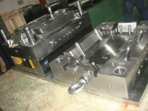
Liquid helped molding is a genuinely old cycle having filled in as a choice to injection molding for china precision plastic injection mold factory. Two varieties of a more current gas help measure with infusion decompression are appeared in Fig. 13.4 [7]. In the primary strategy, two shape parts 10 and 11 structure a form pit 12 into which the plastic dissolve will stream. The trim machine’s spout 13 has an inner center 16 with a sliding valve 19 that is impelled by packed gas on the other hand presented through gas lines 20 and 21 through three-way valves 22 and 23. Toward the start of the interaction, the plastic liquefy 24 is brought into the form pit through the machine spout 13; simultaneously, the sliding valve 19 is in a position which obstructs the gas bay cylinder 18 compacting the gas through line 21 decompressing the gas through line 20. After the form pit is somewhat filled, gas line 20 is compressed while gas line 21 is depressurized. This makes the sliding valve take on the situation as shown so that gas gulf tube 18 is opens and conveys compacted gas to the shape hole. When the gas has been injected, the sliding valve is then incited to forestall the undesired progression of the plastic dissolve. After the formed part cools, the launch of the shape makes the sprue break and the arrival of any packed gas to the surrounding climate.

A subsequent technique is additionally appeared in injection mold manufacturing china in which the opposite of injection pressure, injection decompression, is utilized to mold an empty part with a huge cavity. In this plan, the plastic liquefy streams into a cavity framed between two shape parts 30 and 32. While not appeared, these shape parts can have fine subtleties like supervisors that are full grown by the underlying filling of the depression with the polymer liquefy. The compacted gas is then infused into a thicker segment of the form cavity.

Simultaneously, the mold center 32 is withdrawn from its restricting mold half 30 to develop the cavity. Thusly, moldings with exceptionally huge interior holes (for instance, 50 mm) can be shaped while saving fine highlights on the outside surfaces of the formed part.

This article is from http://www.chinainjectionmold.com/
Split Cavity

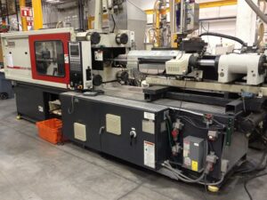
One split hole form configuration is appeared in china high precision mold manufacturer for the trim of bowling pins. The shape incorporates a top brace plate 14, a cavity retainer plate 16, and a help plate 12, among others. The split depression is framed by two moving pit embeds 23 and 24 that mate with the tapered bore 21 in the cavity retainer plate 16 when the form is shut. Four lengthened point pins 30 are secured in the top clip plate and stretch out through the cavity embeds 23 and 24. Every pit embed is attached to two gibs 28 that can cross in slideways 26.

At the point when the shape opens, the help plate 12 is moved away from the cavity retainer plate 16. Since the point pins 30 are fixed and slanted comparative with the form opening bearing, the pit embeds 23 and 24 are compelled to move away from one another through a cam activity. At last, an adequate leeway is delivered between the shaped section 66 and the cavity side dividers 44 with the goal that the formed item might be taken out.

There are a couple of fascinating things to note with respect to this specific split pit shape plan. To start with, there is a lot of shape cheek gave in the hole retainer plate 16. The thickness of the cheek is needed to stay away from unreasonable shear pressure and diversion of the depression side dividers 44. It is seen that the thickness of the cheek is around equivalent to the profundity of the shape depression, as proposed by the investigation of china precision injection plastic parts factory. Second, wear can be an issue in this form configuration because of the enormous mass of the supplements, the length of movement, and the high number of trim cycles. Hence, the gibs should be determined to incorporate lubricity and be effortlessly supplanted when important. Likewise, wear plates should be joined between the help plate 12 and the cavity embeds 23 and 24. Third, interior cooling of the center is given using a huge bubbler 75 with coolant delta 74 and source 76.

Split depression molds have been intended for a long while, and this plan was not chosen exclusively because of its consolidation of a split hole plan. Another fascinating component of the plan is the forward incitation of the center pin 50 during the filling and pressing stages to give infusion pressure forming. This activation is expected to make up for the exceptionally high volumetric shrinkage during the hardening of the thick side dividers 54 of the formed part. Accordingly, the shape configuration incorporates a heading 46 that bolsters the shoulder 65 of the center pin. Since the shaped section 66 will in general therapist onto the center pin 50, the center pin should be withdrawn after the form is opened as appeared in china injection mold factory to deliver the shaped part.

The distance across of financially accessible folding centers goes from 13 to 90 mm, with a breakdown of around 6 % of the center measurement. While their breakdown isn’t close to as much as the plan of precision molds factory, these standard segments uphold completely programmed trim of little highlights, for example, inner strings for shaped terminations. This article is from http://www.chinainjectionmold.com/

Mold Wall

The investigations and plans introduced for mold cooling are sufficient for most inject molding applications in oem/odm automotives mould factory. In any case, there are a few applications wherein the utilization of customary cooling plans is unsatisfactory. Regularly, the improvement of a set skin happens when the hot polymer dissolve contacts the virus form divider. In some trim applications, the solifed skin may prompt untimely freeze off of the liquefy in the pit, unnecessary birefringence in the formed part, or insufficient degrees of sparkle or surface replication. In different applications in china precision injection plastic parts factory, mold divider temperature vacillations over the outside of the form hole may prompt an absence of dimensional control. In that capacity, some trim applications including focal points, plane cockpit overhangs, optical capacity media, and fiber fortified materials may try to improve the nature of the moldings through unique control of the mold divider temperature. A few distinct systems are next examined.

One way to deal with controlling the form divider temperature is to utilize at least one lots of cooling channels to effectively warmth and afterward effectively cool the mold. One such mold configuration is appeared in china high precision mold manufacturer; this was created to give tight resiliences when forming profoundly delicate plastic materials or exceptionally slim walled moldings. In this beat cooling plan, a mold hole 7 is framed by a hole embed 10 and a center supplement 9. The center addition is intentionally intended to be as thin as could be expected under the circumstances, and encompasses an inside center 12 to give a channel 14 to course for temperature controlled liquids. The cavity embed 10 is correspondingly intended to mate with the cavity plate 28 and the external supplement 29 to frame channels 24 and 25.

In activity, two liquids are independently temperature controlled with a warming gadget 35 and a cooling gadget 34; two separate liquids are prescribed to diminish the expense and time related with consecutively warming and cooling a solitary liquid.

Preceding the infusion of the polymer soften, the control valves 36 and 37 will guide the warmed liquid to the delta 18 and through the mold center by means of channels 14 and 15 preceding returning through the outlet 16; a comparative warming circuit is framed for the form hole through components 26, 22, 25, and 27. When the additions 9 and 10 are at a temperature over the point of solidification of the plastic soften, the plastic liquefy is injected into the depression 7. The control valves would then be able to be impelled to coordinate the cooling fl1uids from the cooling gadget 34 through similar channels recently utilized by china injection mold factory for warming.

The achievement of this mold configuration is profoundly reliant on limiting the mass of the form steel and coolant needed to frame and cool the dividers of the mold hole. It is plainly attractive to limit the thickness of the form embeds, the length of the cooling channels and lines, and the warmth move to nearby mold parts. In this plan, air holes 20, 29, and 38 are utilized to lessen the measure of warmth move thus improve the warm effectiveness and dynamic execution of the mold; protecting sheets (not numbered) are additionally given neighboring the top and back cinch plate to limit heat move to the platens. Shockingly, the size of the pit and the basic prerequisites on the form parts requires the utilization of genuinely huge mold segments that should be warmed and therefore cooled. The dynamic warm reaction is restricted.

This article is from http://www.chinainjectionmold.com

Designing Flow

The gas trap in the past model could have been stayed away from by moving the edge entryway to the focal point of the 160 mm long side divider or by utilizing a three plate or hot sprinter form to door at the focal point of the shape cavity, Sometimes, be that as it may, the shape format blocks these plans. Thusly, another option is to change the thickness so the soften deliberately streams quicker in certain segments of the shape. Such thicker segments used to control the stream speed are commonly known as “stream pioneers.” It ought to be perceived that thickness varieties in formed parts from china precision injection plastic parts factory are commonly unwanted as examined by china high precision mold manufacturer. For the reasons talked about in that, the hole thickness variety ought to be kept to a negligible sum.

Newtonian stream investigation will currently be utilized to overhaul the divider thickness of the holder to determine the race following issue. Condition 5.17 relates the weight drop, speed, and thickness. To dispense with the race – following, the weight drop over the centerline should approach the weight drop around the edge.

This condition will guarantee that the stream navigates over the centerline while the stream arrives at the furthest corners of the adjoining side dividers to kill the race – following wonder, The stream lengths are given in Fig. 5.18. From the math of the compartment, the lengths of stream over the centerline and around the side dividers are determined to be 280 mm and 210 mm, separately. This condition will make the liquefy show up at the furthest corner of the side divider simultaneously it arrives at the contrary side of the depression along the centerline.

Subbing this connection into Eq. 5.31 and explaining for the thickness of the side dividers, Hside Walls, as a component of the ostensible thickness, H.

The investigation demonstrates that the divider thickness will be to a great extent corresponding to the proportion of the stream lengths with a lesser reliance on the liquefy viscosities. Accepting a similar consistency all through the pit, the thickness of the side dividers can be assessed.

The lay level examination can likewise be utilized to foresee the filling designs for parts of shifting divider thickness. At the point when the divider thickness differs, it is important to build the radii of the circular segments to speak to the separation that the liquefy went during the time step. For this case, the thickness of the side dividers has been picked.

In the lay level examination, the range of each curve in the more slender area ought to be increased by 75% of the circular segment in the thicker segments. As yet utilizing a similar ghost entryway, the subsequent soften front movement in the updated compartment is appeared. The bolts along the edge of the side divider show the steady position of the dissolve front in this segment at different time steps. The examination demonstrates that the soften arrives at the finish of the side dividers before the liquefy arrives at side of the hole inverse the door.

To approve the lay level methodology, mathematical recreations were performed for the holder having a uniform thickness of2 mm and a second compartment in which the thickness of the side dividers was diminished to 1.5 mm.

As in the lay level examinations by china injection mold factory, the recreation demonstrated that the compartment without the stream chief would show race-following, a weld line, and a gas trap. Lessening the thickness of the side dividers to 1.5 mm killed the issues. For reference, the decrease in the thickness of the side divider from 2 mm to 1.5 mm increased the infusion pressure by 10% to round out the more slender side dividers yet in addition diminished the part weight by a comparable sum. This article is from http://www.chinainjectionmold.com