Split Cavity

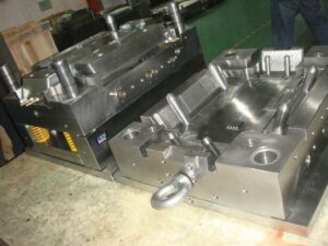
One split hole form configuration is appeared in china high precision mold manufacturer for the trim of bowling pins. The shape incorporates a top brace plate 14, a cavity retainer plate 16, and a help plate 12, among others. The split depression is framed by two moving pit embeds 23 and 24 that mate with the tapered bore 21 in the cavity retainer plate 16 when the form is shut. Four lengthened point pins 30 are secured in the top clip plate and stretch out through the cavity embeds 23 and 24. Every pit embed is attached to two gibs 28 that can cross in slideways 26.

At the point when the shape opens, the help plate 12 is moved away from the cavity retainer plate 16. Since the point pins 30 are fixed and slanted comparative with the form opening bearing, the pit embeds 23 and 24 are compelled to move away from one another through a cam activity. At last, an adequate leeway is delivered between the shaped section 66 and the cavity side dividers 44 with the goal that the formed item might be taken out.

There are a couple of fascinating things to note with respect to this specific split pit shape plan. To start with, there is a lot of shape cheek gave in the hole retainer plate 16. The thickness of the cheek is needed to stay away from unreasonable shear pressure and diversion of the depression side dividers 44. It is seen that the thickness of the cheek is around equivalent to the profundity of the shape depression, as proposed by the investigation of china precision injection plastic parts factory. Second, wear can be an issue in this form configuration because of the enormous mass of the supplements, the length of movement, and the high number of trim cycles. Hence, the gibs should be determined to incorporate lubricity and be effortlessly supplanted when important. Likewise, wear plates should be joined between the help plate 12 and the cavity embeds 23 and 24. Third, interior cooling of the center is given using a huge bubbler 75 with coolant delta 74 and source 76.

Split depression molds have been intended for a long while, and this plan was not chosen exclusively because of its consolidation of a split hole plan. Another fascinating component of the plan is the forward incitation of the center pin 50 during the filling and pressing stages to give infusion pressure forming. This activation is expected to make up for the exceptionally high volumetric shrinkage during the hardening of the thick side dividers 54 of the formed part. Accordingly, the shape configuration incorporates a heading 46 that bolsters the shoulder 65 of the center pin. Since the shaped section 66 will in general therapist onto the center pin 50, the center pin should be withdrawn after the form is opened as appeared in china injection mold factory to deliver the shaped part.

The distance across of financially accessible folding centers goes from 13 to 90 mm, with a breakdown of around 6 % of the center measurement. While their breakdown isn’t close to as much as the plan of precision molds factory, these standard segments uphold completely programmed trim of little highlights, for example, inner strings for shaped terminations. This article is from http://www.chinainjectionmold.com/
Designing Flow

The gas trap in the past model could have been stayed away from by moving the edge entryway to the focal point of the 160 mm long side divider or by utilizing a three plate or hot sprinter form to door at the focal point of the shape cavity, Sometimes, be that as it may, the shape format blocks these plans. Thusly, another option is to change the thickness so the soften deliberately streams quicker in certain segments of the shape. Such thicker segments used to control the stream speed are commonly known as “stream pioneers.” It ought to be perceived that thickness varieties in formed parts from china precision injection plastic parts factory are commonly unwanted as examined by china high precision mold manufacturer. For the reasons talked about in that, the hole thickness variety ought to be kept to a negligible sum.

Newtonian stream investigation will currently be utilized to overhaul the divider thickness of the holder to determine the race following issue. Condition 5.17 relates the weight drop, speed, and thickness. To dispense with the race – following, the weight drop over the centerline should approach the weight drop around the edge.

This condition will guarantee that the stream navigates over the centerline while the stream arrives at the furthest corners of the adjoining side dividers to kill the race – following wonder, The stream lengths are given in Fig. 5.18. From the math of the compartment, the lengths of stream over the centerline and around the side dividers are determined to be 280 mm and 210 mm, separately. This condition will make the liquefy show up at the furthest corner of the side divider simultaneously it arrives at the contrary side of the depression along the centerline.

Subbing this connection into Eq. 5.31 and explaining for the thickness of the side dividers, Hside Walls, as a component of the ostensible thickness, H.

The investigation demonstrates that the divider thickness will be to a great extent corresponding to the proportion of the stream lengths with a lesser reliance on the liquefy viscosities. Accepting a similar consistency all through the pit, the thickness of the side dividers can be assessed.

The lay level examination can likewise be utilized to foresee the filling designs for parts of shifting divider thickness. At the point when the divider thickness differs, it is important to build the radii of the circular segments to speak to the separation that the liquefy went during the time step. For this case, the thickness of the side dividers has been picked.

In the lay level examination, the range of each curve in the more slender area ought to be increased by 75% of the circular segment in the thicker segments. As yet utilizing a similar ghost entryway, the subsequent soften front movement in the updated compartment is appeared. The bolts along the edge of the side divider show the steady position of the dissolve front in this segment at different time steps. The examination demonstrates that the soften arrives at the finish of the side dividers before the liquefy arrives at side of the hole inverse the door.

To approve the lay level methodology, mathematical recreations were performed for the holder having a uniform thickness of2 mm and a second compartment in which the thickness of the side dividers was diminished to 1.5 mm.

As in the lay level examinations by china injection mold factory, the recreation demonstrated that the compartment without the stream chief would show race-following, a weld line, and a gas trap. Lessening the thickness of the side dividers to 1.5 mm killed the issues. For reference, the decrease in the thickness of the side divider from 2 mm to 1.5 mm increased the infusion pressure by 10% to round out the more slender side dividers yet in addition diminished the part weight by a comparable sum. This article is from http://www.chinainjectionmold.com