Split Cavity

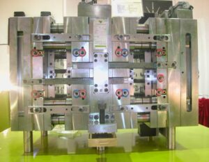
One split hole form configuration is appeared in china high precision mold manufacturer for the trim of bowling pins. The shape incorporates a top brace plate 14, a cavity retainer plate 16, and a help plate 12, among others. The split depression is framed by two moving pit embeds 23 and 24 that mate with the tapered bore 21 in the cavity retainer plate 16 when the form is shut. Four lengthened point pins 30 are secured in the top clip plate and stretch out through the cavity embeds 23 and 24. Every pit embed is attached to two gibs 28 that can cross in slideways 26.

At the point when the shape opens, the help plate 12 is moved away from the cavity retainer plate 16. Since the point pins 30 are fixed and slanted comparative with the form opening bearing, the pit embeds 23 and 24 are compelled to move away from one another through a cam activity. At last, an adequate leeway is delivered between the shaped section 66 and the cavity side dividers 44 with the goal that the formed item might be taken out.

There are a couple of fascinating things to note with respect to this specific split pit shape plan. To start with, there is a lot of shape cheek gave in the hole retainer plate 16. The thickness of the cheek is needed to stay away from unreasonable shear pressure and diversion of the depression side dividers 44. It is seen that the thickness of the cheek is around equivalent to the profundity of the shape depression, as proposed by the investigation of china precision injection plastic parts factory. Second, wear can be an issue in this form configuration because of the enormous mass of the supplements, the length of movement, and the high number of trim cycles. Hence, the gibs should be determined to incorporate lubricity and be effortlessly supplanted when important. Likewise, wear plates should be joined between the help plate 12 and the cavity embeds 23 and 24. Third, interior cooling of the center is given using a huge bubbler 75 with coolant delta 74 and source 76.

Split depression molds have been intended for a long while, and this plan was not chosen exclusively because of its consolidation of a split hole plan. Another fascinating component of the plan is the forward incitation of the center pin 50 during the filling and pressing stages to give infusion pressure forming. This activation is expected to make up for the exceptionally high volumetric shrinkage during the hardening of the thick side dividers 54 of the formed part. Accordingly, the shape configuration incorporates a heading 46 that bolsters the shoulder 65 of the center pin. Since the shaped section 66 will in general therapist onto the center pin 50, the center pin should be withdrawn after the form is opened as appeared in china injection mold factory to deliver the shaped part.

The distance across of financially accessible folding centers goes from 13 to 90 mm, with a breakdown of around 6 % of the center measurement. While their breakdown isn’t close to as much as the plan of precision molds factory, these standard segments uphold completely programmed trim of little highlights, for example, inner strings for shaped terminations. This article is from http://www.chinainjectionmold.com/

Slides

To give as protected and proficient a shape as could reasonably be expected, the form creator ought to indicate the utilization of limit changes to affirm that the moving center is in its forward or withdrawn position, These position signs can be utilized by the embellishment machine to guarantee that the moving centers are appropriately situated to not harm the formed parts or the infusion form during mold opening or part discharge. Moreover, the form architect ought to endeavor to plan the moving center with the end goal that the shape opening or part discharge doesn’t harm the shape if the moving center is inappropriately situated. Consider, for instance, the plan appeared in china high precision mold supplier. On the off chance that the shape is opened and the part shot out with the pushing center in its ahead position, all things considered, the plastic part will be sheared off at the essential rib by the incitation of the close by ejector sleeve and ejector edge. Clearly, this occasion is undesired and ought not happen for an appropriately set embellishment measure. Notwithstanding, such occasions do happen and decays enormously like a powerful form plan that can withstand discontinuous maltreatment without adjusting the ejector pins, cutting edges, sleeves, or moving centers.

Center pulls are very regular since they permit moving supplements to be activated in various ways, strokes, and times. In any case, center pulls require actuators, auxilliary control, and huge space. Therefore, form originators regularly like to utilize sliding centers that are incited by slanted point pins.

One such shape configuration is appeared in oem/odm industrial injection mold design factory. In this plan, a bronze gib is situated in the B plate to give a greased up sliding surface to the moving supplement. The center addition is furnished with a slanted can surface that mates with the point pin, As the form opens and shuts, the point pin draws in the sliding center, making the center move in and out. A retainer plate made sure about to the B plate keeps the sliding center from dropping out of the gib.

The point by point configuration is appeared in china custom mold components and warrants further conversation. The point pin is situated using a point pin embed, which has a level surface to arrange the point pin toward the sliding activity. While there are numerous approaches to plan a slide for side activity, the point pin embed is held between the center addition and a heel block by attachment head cap fastens this plan. On the moving side of the shape, the bronze gib is situated with dowels and affixed with cap sinks to a pocket cut the B plate and center supplement. The gib gives a keyway into which directs the sliding center. The sliding center itself is fundamentally the same as that recently appeared in oem/odm industrial injection moulding factory.

In activity, the clasping of the shape makes two powers be forced on the sliding center. To start with, the calculated surface on the heel block contacts the calculated surface on the slide to constrain the slide along the side against the center addition; this parallel power withstands the dissolve pressure and forestalls blazing of the ribs, supervisors, and window. Second, the pit embed contacts the top surface of the slide, which gives a descending clasping power to forestall redirection and glimmering around the splitting line of the trim. It should be noticed that the point pin doesn’t give the sidelong power and isn’t exposed to huge pressure in this plan. All around planned clearances, resiliences, and fits are pivotal to the capacity and life span of the sliding center.

This article is from http://www.chinainjectionmold.com

Ejector Pin

The bigger freedom between the ejector pin and the ejector through-opening not just serves to wipe out the sliding rubbing between the pin and the plate, yet in addition gives required slop to permit to misa lignment between the tomahawks of the ejector openings in different plates. The predetermined freedom ought to surpass the absolute stack-up of the openings’ positional resiliences over the form plates. Since ordinary boring resiliences are on the request for 0.25 mm, a diametral leeway of 0.5 mm should be adequate in most shape making applications. Moreover, a liberal chamfer should be given at the interface between the center addition and the help plate. As shown in china high-precision mould suppliers, this chamfer helps the controlling of the ejector pin from the help plate into the center addition during mold get together.

The definite plan of the ejector retainer plate is appeared in injection moulding services china. As appeared in Detail D, a counterbore is given in the ejector retainer plate to pull the top of the ejector pin(s) away from the splitting plane of the shape when the ejector framework is being withdrawn. To give leeway to misalignment of the places of the ejector openings, the counterbore is given a liberal resilience so the centerline of every ejector pin is represented by the mating of the pin with the reamed ejector opening in the center supplements. In the event that a shaped pin is utilized, the top of the pin is normally given a level as appeared in Detail E. An equal space and finding dowel are given in the ejector retainer plate to keep up the right direction of the formed ejector pin.

At whatever point conceivable, the shape architect ought to indicate a similar length and width of ejector pins to encourage form gathering and upkeep. On the off chance that distinctive ejector pins are utilized in the form plan, the shape fashioner and shape creator should make certain to key and name every ejector pin and coordinating area on the ejector retainer plate so the shape can be promptly kept up by the disintegrate. The form fashioner ought to consistently try not to plan ejector sticks that fluctuate just somewhat in their plan, since comparable pins may incidentally be viewed as exchangeable by the disintegrate.


The erroneous gathering of ejector pins may make harm the pins just as the restricting mold hole surfaces.

Ejector pins are normally hot manufactured and rotundly ground from hard prepares, (for example, H 13). Stubsequently, the pins are nitrided and cleaned to give an exceptionally hard and smooth surface for low wear and rubbing. Ejector pins are accessible from a few providers in standard measurements (going from 1 mm to 25 mm) and lengths (from 150 1mm to 500 mm). Ordinarily, form creators cut and pound standard ejector pins to the completed length and shape indicated in the shape plan. Be that as it may, ejector pins might be exclusively requested with changing alternatives including distinctive mate rials or surface treatuments, exact diarneters or lengths, strings for mating with the ejector plate, pads, grooves, and so forth While ejector pins are accessible in a scope of breadths and lengths, particularly long pins with little distances across should be dodged, The explanation is that such thin pins will in general clasp under burden. As appeared in plastic injection moulded components china, the stacking of an ejector pin relates to a section with the top end upheld by the drag of the ejector opening, and the base end stuck by the ejector retainer plate. On the off chance that the compressive burden become too huge, at that point the pin may bow or lock an obscure way.

This article is from http://www.chinainjectionmold.com/

Ejection Push Part

When the launch powers on the embellishment have been assessed, the following stage is to decide the total”push territory” of the ejectors onto the shaped part. In particular, there is a base push territory that is needed to maintain a strategic distance from inordinate compressive weight on the discharge system segments just as unnecessary shear weight on the plastic moldings. These two marvels are represented by china mould design services for a solitary pin shooting a bit of the PC bezel.

At the point when the pin is activated with the discharge framework, a response power, Fpin, will create between the pin and the shaped part before the part is shot out. The greatness of this power is identified with the all out discharge power needed to launch the part just as the number, area, and math of the ejectors. The compressive stres on the pin, Opin, is the power on the pin isolated by the region of the pin, or: σpin=Fpin/Aacompession

To stay away from exhaustion or potentially clasping of the launch framework segments, compressive feelings of anxiety must be kept up under a basic edge. This basic pressure, 0 fatigue_ limit is needy upon the material and treatment of the ejectors. Most ejector pins and sleeves are made of solidified materials, with exhaustion limit weights on the request for 800 MPa. A traditionalist shape plan, notwithstanding, may expect a lower weariness limit pressure of 450 MPa for P20. In one or the other case, the all out push territory, all things considered, Aejectors, to keep away from over the top compressive anxieties must meet the necessity.

The necessary push territory to evade abundance compressive anxieties in the discharge framework is exceptionally little in most trim applications invigorated the moderately high of steel. High-precision molds made in china know that the compressive quality of the pins is accordingly not compelling the plan.

Be that as it may, the ejector framework should likewise have enough push zone to try not to create exorbitant shear stresses in the shaped parts upon discharge. For oem/odm industrial injection moulding design factory, the shear pressure applied on the formed part is the power on the pin separated by the territory of the shaped part straightforwardly over the boundary of the pin, or: :

where Qnin is the border of the pin. In the event that the shear pressure in the shaped part is too high, at that point the part can for all time mutilate close to the pin (an impact known as”push pin”), forever twist, or even crack. To dodge these deformities, the form should be planned with the end goal that the edge around all the ejectors gives a shear pressure short of what one-a large portion of the yield pressure of the material, Oplastic veld. This prerequisite prompts the accompanying relationship for the all out border of the ejector framework.

The examination and models show that for most trim applications, the plan of the ejector framework is driven more by the yield stresses applied on the plastic embellishment as opposed to by the compressive weights on the pin. Notwithstanding, compressive pressure can cause locking in long, thin individuals, for example, ejector pins. Consequently, further investigation of the compressive anxieties is significant, and will be accordingly used to dodge pin clasping. This article is from http://www.chinainjectionmold.com