Ejection Push Part

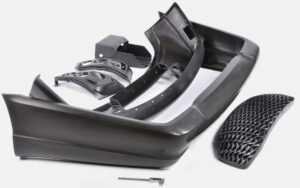
When the launch powers on the embellishment have been assessed, the following stage is to decide the total”push territory” of the ejectors onto the shaped part. In particular, there is a base push territory that is needed to maintain a strategic distance from inordinate compressive weight on the discharge system segments just as unnecessary shear weight on the plastic moldings. These two marvels are represented by china mould design services for a solitary pin shooting a bit of the PC bezel.

At the point when the pin is activated with the discharge framework, a response power, Fpin, will create between the pin and the shaped part before the part is shot out. The greatness of this power is identified with the all out discharge power needed to launch the part just as the number, area, and math of the ejectors. The compressive stres on the pin, Opin, is the power on the pin isolated by the region of the pin, or: σpin=Fpin/Aacompession

To stay away from exhaustion or potentially clasping of the launch framework segments, compressive feelings of anxiety must be kept up under a basic edge. This basic pressure, 0 fatigue_ limit is needy upon the material and treatment of the ejectors. Most ejector pins and sleeves are made of solidified materials, with exhaustion limit weights on the request for 800 MPa. A traditionalist shape plan, notwithstanding, may expect a lower weariness limit pressure of 450 MPa for P20. In one or the other case, the all out push territory, all things considered, Aejectors, to keep away from over the top compressive anxieties must meet the necessity.

The necessary push territory to evade abundance compressive anxieties in the discharge framework is exceptionally little in most trim applications invigorated the moderately high of steel. High-precision molds made in china know that the compressive quality of the pins is accordingly not compelling the plan.

Be that as it may, the ejector framework should likewise have enough push zone to try not to create exorbitant shear stresses in the shaped parts upon discharge. For oem/odm industrial injection moulding design factory, the shear pressure applied on the formed part is the power on the pin separated by the territory of the shaped part straightforwardly over the boundary of the pin, or: :

where Qnin is the border of the pin. In the event that the shear pressure in the shaped part is too high, at that point the part can for all time mutilate close to the pin (an impact known as”push pin”), forever twist, or even crack. To dodge these deformities, the form should be planned with the end goal that the edge around all the ejectors gives a shear pressure short of what one-a large portion of the yield pressure of the material, Oplastic veld. This prerequisite prompts the accompanying relationship for the all out border of the ejector framework.

The examination and models show that for most trim applications, the plan of the ejector framework is driven more by the yield stresses applied on the plastic embellishment as opposed to by the compressive weights on the pin. Notwithstanding, compressive pressure can cause locking in long, thin individuals, for example, ejector pins. Consequently, further investigation of the compressive anxieties is significant, and will be accordingly used to dodge pin clasping. This article is from http://www.chinainjectionmold.com

Heat transfer Control

oem/odm industrial injection moulding design factory should take the heat transfer into consideration when making the inject molds. Given the troubles related with dynamic shape divider temperature control, a “latent” cooling configuration has been created by china high precision mold manufacturer; the expression “passive”is used to suggest that the form doesn’t use any outside capacity to control the form divider temperature. The plan appeared in injection mould factory was explicitly evolved to control the shape divider temperature during the embellishment of optical media. The shape incorporates two parts 12 to frame a form hole 14. Cooling lines 20 are given for each traditional plan to eliminate the warmth from the polymer soften. Notwithstanding, a warm protecting part 22 is put between the shape parts 12 and the stampers 31 and 33. The warm protecting part 22 is produced using a low thermally conductive material, ideally a high temperature polymer, for example, polyimides, polyamideimides, polyamides, polysulfone, polyethersulfone, polytetrafluoroethylene, and polyetherketone. The protecting polymer is normally turn covered in an uncured structure to give a layer a thickness on the request for 0.25 mm and accordingly heat relieved. The stamper 33 is commonly manufactured from nickel, and gives the surface subtleties to replication while additionally ensuring and giving the separator a uniform, exceptionally cleaned surface during embellishment.

During embellishment, the protecting layer 22 behind the stamper 33 eases back the underlying cooling of the tar during the trim activity. Due to this protection, the stamper’s temperature increments and s0 the skin layer holds heat longer during the shape filling stage, accordingly staying away from the surface anomalies made by quick surface cooling. The temperature of the stamper:melt interface can be constrained by determination of the cycle conditions just as the layers’ thicknesses and material properties; one dimensional cooling examination can be utilized by plastic precision injection mould factory to comprehend the physical science and aid the plan streamlining. In this model, it was discovered that the centerline temperature 51 of the plate directs the base cooling time for the part to cool underneath the glass change temperature of the polymer dissolve. The temperature 52 at the stamper:melt interface impacts the warm pressure and pit replication on the circle’s surface and is estimated. The temperature 53 in the form behind the separator recommends that the shape goes about as a warmth sink and is kept up at a significantly steady temperature.

The shape fashioner and measure specialist ought to instinctively comprehend that the expansion of a protecting layer will in general diminish the pace of warmth move from the soften to the form, and in this way require expanded cooling times. To lighten this issue, the cooling lines can be worked at a lower temperature to accommodate higher paces of warmth move after the underlying warming of the stamper. Likewise, this plan methodology for the plastic injection moulded components china gives a sensible degree of shape divider temperature control with no extra energy utilization or control frameworks. Nonetheless, the degree of temperature control is restricted contrasted with the other air conditioning tive warming plans. Furthermore, this methodology might be dififcult to apply to complex three-dimensional calculations.

This article is from http://www.chinainjectionmold.com/.

Pressure Drop and Gate Freeze

In the event that in oem/odm industrial injection moulding design factory the shear rates are inside as far as possible, at that point the weight drops are likely satisfactory too, However, the weight drop through the entryway ought to be determined to guarantee that sufficient infusion pressure is accessible to fill the shape pit; door measurements can likewise be acclimated to change the area of weld-lines in the form cavity. The weight drops are determined by the recently given conditions to gooey stream in strips and chambers. For reference, the formulae for Newtonian and force law streams are given.

In assessing the weight drop through doors, it is essential to figure the consistency at the fitting shear rate when utilizing the Newtonian model, or on the other hand utilize the conditions for the force law model. The weight drop through the doors may shift from right around zero to a few MPa. Weight drops over 10 MPa are normally characteristic of inappropriately planned entryways that are either excessively slight or excessively long.

After the shape depression is loaded up with the polymer soften, extra material must be constrained into the hole to make up for volumetric shrinkage as the dissolve cools. As the liquefy in the hole cools, the soften in the entryway will likewise will in general cool. The solidified skin will engender from the form divider to the centerline of the entryway. Since no extra soften stream can be provided to the cavity once the door freezes, the disintegrate should set up the embellishment machine to end the pressing stage at entryway freeze off and start the plastication stage. The door freeze time must be adequate to take into account pressing of the polymer in the form depression.

The cooling of the liquefy in the cavity and the utilization of the related warmth condition will be talked about in pom moulding parts manufacturers china. Utilizing the gave investigation, the mass liquefy temperature is plotted as a component of time for a 2 mm measurement barrel shaped entryway for ABS at midrange dissolve and coolant temperatures. The mass temperature of the polymer in the door will at first be near the set dissolve temperature of 240°C,and at that point decline in the post-filling stage as the warmth moves to the colder shape dividers. It would in the end arrive at the shape coolant temperature of 80°C.

Injection molding service china utilizing the Cross WLF consistency model, the evident thickness of the polymer dissolve in the door at a shear pace of 10 1/s is likewise plotted in Fig. 7.18. It is seen that the consistency of the plastic liquefy is at first low, and afterward starts to increment exponentially as the temperature diminishes. In the end, the consistency will increment with the end goal that no stream is successfully communicated through the entryway and the pressing stage should end, For this situation, a thickness of 100,000 Pa s has been subjectively chosen as a”no-stream” condition, relating to a door freeze season of about 1.5 s. Supplement A gives the “no-stream temperature”for different materials assessed as such.

For reference, the conditions to ascertain the door freeze time are accommodated rectilinear and strip calculations. These conditions will give the base pack times since they expect flawless warmth conduction between the soften and the shape divider. Practically speaking, entryway freeze times will be longer since these conditions don’t consider the soften course through the door into the hole and the related convection of warmth that will in general forestall the freezing of the entryway. Hence, the length of the pressing stage ought to be relied upon to be fairly longer than those anticipated with the conditions. All things being equal, the conditions are helpful to give a gauge of the significant degree of the polymer cementing time in the entryway.

This article is from http://www.chinainjectionmold.com.

Valve Gate

Hot runner providers of injection moulding services china have attempted to determine these issues, however with restricted achievement. For trim applications including continuous shading changes or the utilization of shear touchy or intensely filled materials, it is alluring to smooth out the move through the door and lessen the shear rates. As needs be, the warm sprue door configuration has been created. In this plan from mould manufacturers factory, a spout tip is used that has a long contact length with the encompassing mold. This permits the entryway territory at the cavity to cool essentially, with the end goal that no protecting layer of plastic is required. An open stream bore inside the spout and spout tip would then be able to control the plastic liquefy legitimately to the pit. After the dissolve fills the form, the whole sprue beneath the warm entryway soldifies. A lot of combining veering tightens in the spout tip directs the break purpose of the sprue, leaving a slim layer of set plastic behind to seal the plastic dissolve.

Contrasted with the warm pin-point entryway, the warm sprue door furnishes an open stream held on for decreased shear rates and weight drop. Since the shear rates are decreased, the warm sprue entryway is more qualified for use with shear delicate and vigorously filled materials. Because of its open stream bore, besides, the warm sprue door normally requires less embellishment cycles when hues 0r materials are changed.

One less obvious yet significant preferred position is that the length of the sprue can be intended to permit freedom for ribs or other cavity subtleties that exude towards the feed framework and may forestall direct gating with a warm pin-point door. There is one noteworthy weakness of the warm sprue door, in any case. Since a sprue is moldd with the part, it must stay with the part as remnant or in any case be later disengaged by the administrator or another post-forming measure.

Warm doors are efficient and by and large reasonable for a wide scope of trim applications and materials. Be that as it may, both the pin-point and sprue warm doors have two expected restrictions. To begin with, they depend on a set layer of plastic to forestall spillage, and this set layer may not be adequate in an assortment of conditions. Second, warm doors give a huge entryway remnant that may not be worthy in numerous applications. To determine the impediments of the warm door, precisely impelled valve entryways have been created. During activity, the valve pin is withdrawn to give admittance to the mold cavity. After the pit is filled and pressed, the valve pin is progressed to seal the door.

Valves entryways have in any event three critical points of interest over warm doors. To start with, valve entryways give a mechanical seal (steel on steel) as are more powerful regarding forestalling melt spillage. Second, the essence of the valve pin presents a mold shut-off surface to the form cavity when shut and along these lines altogether lessens the door remnant. Third, opening and shutting of valve pins might be planned to successively fill multigated mold in order to dispose of weave lines or deliberately control pressing weights to improve part quality.

Lamentably, valve entryways increment the expense and multifaceted nature of the mold, The costis expanded because of the expansion of the valve pins, actuators, and a lot bigger top clip plate to house the actuators, hoses, fittings, and the control framework. In that capacity, the expense of a hot runner framework with valve doors might be double the expense of a hot runner system with warm entryways. Intricacy in activity of china high-precision mould suppliers is additionally expanded, as the administrator should effectively interface the hoses and determine timings to agree with the cycle settings on the embellishment machine.

This article is from http://www.chinainjectionmold.com

Mold Partial Design

For china high-precision mould suppliers, the expression “parting line” alludes to the area at which the pit embed, the center addition, and the plastic trim meet. Since the center and depression embed meet at this area, any huge avoidance of the cavity embed away from the center supplement will bring about a hole into which the plastic will stream and structure a dainty film of plastic known as “streak.” Imperfections in the center and cavity embeds at this area, for example because of wear or inappropriate dealing with, will likewise make holes into which the plastic will stream. Indeed, even with new and all around made molds, the area of the splitting line as a rule brings about a slight “witness line” along its length.

Therefore, the splitting line ought to be situated along a base edge of the part, or some other non-visual, nonfunctional edge. Think about the past cup. Setting the splitting line extremely near the lip as shown by the ran line in the left drawing would bring about an observer line and conceivable glimmer that may make the molded cup unusable. A superior area for the splitting line is at the base of the edge as demonstrated, relating to the splitting line.

During injection moulding services china, for the PC bezel, the splitting line will be situated around the base edge of the part. It is seen that, in contrast to the cup, the splitting line for the bezel isn’t in a solitary plane. Or maybe, the splitting line follows the profile of the highlights as an afterthought dividers. This separating line is needed to fit the center addition, which hollows out the mold cavity to frame the openings required for the different connectors. As will be found in the following area, this mind boggling separating line mold will cause a more perplexing splitting plane.

When the splitting line is recognized, the splitting plane is extended outwards from the part to isolate the center supplement from the hole embed. The pit addition will mold the external and top surfaces of the part, while the center supplement will frame the edge and internal surfaces. For the PC bezel, the splitting line can be transmitted outward to frame the splitting surface. It tends to be seen that the entirety of the out-of-plane highlights along the splitting line n0w become complex surfaces on the splitting plane.

These surfaces present two huge issues during mold activity. To begin with, any misalignment between the sharp highlights on center and depression additions will cause wear between the sliding surfaces if not an inside and out effect between the main edge of the center and the mating pit surface. Second, the brace weight applied on the center and depression additions can make the surfaces lock along with outrageous power, causing exorbitant pressure and potential mold twisting during mold activity of china injection design service.

To evade inordinate pressure, interlocking highlights on the splitting plane ought to be slanted at any rate five degrees comparative with the mold opening course. The splitting surface is presently regularly made by means of three-dimensional PC supported plan (“3D CAD”) utilizing lobbed surfaces. Each hurled surface mixes a bended element along the splitting line to a line of comparing width on the splitting plane. The outcome is a surface with the required profile at the splitting line and the important draft down to the splitting plane. The hurled surfaces are then weave along with the splitting plane to give a splitting surface, as appeared for the bezel. These surfaces might be legitimately machined utilizing PC mathematically controlled (CNC) machining 0r by means of plunge electrical release machining (EDM) utilizing at least one anodes that were CNC machined.

This article is from http://www.chinainjectionmold.com/.