Turning Center

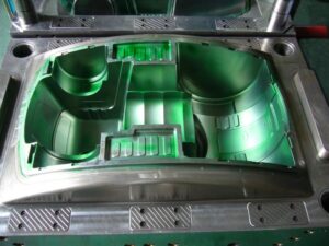
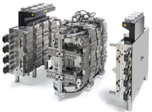
Folding centers are generally easy to fuse into shape plans when utilizing a bought gathering, and can be utilized for the framing of strings, dimples, windows, and other interior highlights. Be that as it may, one issue with folding centers is the development of witness lines on the inside of the shaped part where the center portions interface. Depending 0n the application necessities, these observer lines may disallow the utilization of the folding centers. In that capacity, various shape plans have been created with turning centers for the arrangement and demolding of inner strings. One plan is shown in oem/odm industrial injection moulding design factory for a 64 depression form for the creation of strung covers [13]. The shape configuration incorporates cavities 16 that are framed by coordinating arrangements of hole embeds 10 and center supplements 15. The rear of each center incorporates a vital help 17, which is mounted upon a shaft 18 that reaches out from a coarsely strung helix 19. The helix is pivotally situated between the back brace plate 21 and the help plate 23, and radially upheld by course 20 and 26.

1

Devotee pins 30 have been fitted to the incited plate 29 that connect with the strings of the helix 19. Since these pins can’t pivot, the activation of the plate 29 will cause the revolution of the helix 19, and the resulting turn of the strung centers 15. Concerning plan, a coarsely strung helix is fundamental since the force and wear will increment considerably as the pitch diminishes. All things considered, the necessary length of the helix is identified with the erosion between the helix and the supporter, just as the quantity of pivots in the embellishment application.

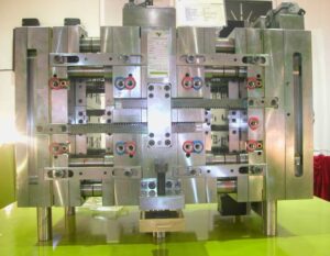
Another shape plan for turning centers is appeared in the arrangement perspective on mould manufacturers china. In this form plan, a focal sun gear 84 at the same time activates different planetary pinion wheels 86, which thus drive shafts 88. The center supplements are not appeared in plastic molding services china, however are keyed to the drive shafts through spaces 66. There are numerous potential plans to turn the sub stuff 84. In this plan, a pinion 42 is connected to a shaft 74 which closes at a slope gear 76. This slope gear 76 lattices with another slant gear 78 that is bolted to the focal sun gear 84. In activity, the form opening stroke causes

■the rack 44 to draw in the pinion 42,

■the pinion 42 to pivot the shaft 74,

■ the shaft 74 to pivot the incline gear 76,

■the slope gear 76 to pivot the incline gear 78,

■the slant gear 78 to turn the sun gear 84,

■ the sun stuff to pivot the planetary cog wheels 86,

■ the planetary cog wheels 86 to turn the shaft 88, and

■the shaft 88 to pivot the centers keyed to opening 66.

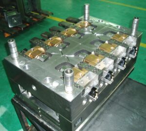
With either plan procedure, the high-precision molds made in china ought to guarantee that the part calculation is intended to forestall the turn of the shaped part with the pivoting center. Now and again, the sprinter and door may give adequate solidarity to forestall the formed part’s revolution. In different cases, nonetheless, this methodology is insufficient since the discharge powers will in general shift with the material properties, preparing conditions, and surface completion as examined before in china mould design services. Therefore, the mold configuration may utilize some little undermines or other nonasymmetric highlights to forestall the part revolution.

This article is from http://www.chinainjectionmold.com/

Pressure Drop and Gate Freeze

In the event that in oem/odm industrial injection moulding design factory the shear rates are inside as far as possible, at that point the weight drops are likely satisfactory too, However, the weight drop through the entryway ought to be determined to guarantee that sufficient infusion pressure is accessible to fill the shape pit; door measurements can likewise be acclimated to change the area of weld-lines in the form cavity. The weight drops are determined by the recently given conditions to gooey stream in strips and chambers. For reference, the formulae for Newtonian and force law streams are given.

In assessing the weight drop through doors, it is essential to figure the consistency at the fitting shear rate when utilizing the Newtonian model, or on the other hand utilize the conditions for the force law model. The weight drop through the doors may shift from right around zero to a few MPa. Weight drops over 10 MPa are normally characteristic of inappropriately planned entryways that are either excessively slight or excessively long.

After the shape depression is loaded up with the polymer soften, extra material must be constrained into the hole to make up for volumetric shrinkage as the dissolve cools. As the liquefy in the hole cools, the soften in the entryway will likewise will in general cool. The solidified skin will engender from the form divider to the centerline of the entryway. Since no extra soften stream can be provided to the cavity once the door freezes, the disintegrate should set up the embellishment machine to end the pressing stage at entryway freeze off and start the plastication stage. The door freeze time must be adequate to take into account pressing of the polymer in the form depression.

The cooling of the liquefy in the cavity and the utilization of the related warmth condition will be talked about in pom moulding parts manufacturers china. Utilizing the gave investigation, the mass liquefy temperature is plotted as a component of time for a 2 mm measurement barrel shaped entryway for ABS at midrange dissolve and coolant temperatures. The mass temperature of the polymer in the door will at first be near the set dissolve temperature of 240°C,and at that point decline in the post-filling stage as the warmth moves to the colder shape dividers. It would in the end arrive at the shape coolant temperature of 80°C.

Injection molding service china utilizing the Cross WLF consistency model, the evident thickness of the polymer dissolve in the door at a shear pace of 10 1/s is likewise plotted in Fig. 7.18. It is seen that the consistency of the plastic liquefy is at first low, and afterward starts to increment exponentially as the temperature diminishes. In the end, the consistency will increment with the end goal that no stream is successfully communicated through the entryway and the pressing stage should end, For this situation, a thickness of 100,000 Pa s has been subjectively chosen as a”no-stream” condition, relating to a door freeze season of about 1.5 s. Supplement A gives the “no-stream temperature”for different materials assessed as such.

For reference, the conditions to ascertain the door freeze time are accommodated rectilinear and strip calculations. These conditions will give the base pack times since they expect flawless warmth conduction between the soften and the shape divider. Practically speaking, entryway freeze times will be longer since these conditions don’t consider the soften course through the door into the hole and the related convection of warmth that will in general forestall the freezing of the entryway. Hence, the length of the pressing stage ought to be relied upon to be fairly longer than those anticipated with the conditions. All things being equal, the conditions are helpful to give a gauge of the significant degree of the polymer cementing time in the entryway.

This article is from http://www.chinainjectionmold.com.

Feeding Amount for the Feed System

To accomplish the best feed system structure, the form fashioner ought to indicate the widths of the feed system to mutually limit the weight drop and the feed system volume. These plan imperatives are spoken by oem/odm largest plastic injection molding companies. As the breadths of the different fragments of the feed system increment, the weight drop diminishes underneath the predetermined greatest. Nonetheless, expanding the widths of the feed system additionally brings about an expansion in the volume of the feed system, which can be unwanted for both cold and hot sprinter feed systems.

In chilly sprinter structures, the enormous size of the feed system can bring about expanded process durations just as inordinate material waste related with the embellishment of the feed system. Some embellishment applications permit the utilization of regrind blended in with virgin material. An average breaking point on regrind might be 30%, which makes an interpretation of legitimately to a particular on the greatest volume of the feed system. For instance, in high precision plastic making mould china, on the off chance that a trim application had two pits adding up to 50 CC, at that point a 30% regrind detail would restrict the volume of the feed system to 15 CC.

In hot sprinter plans, huge feed systems lessen the turnover of the material in the hot sprinter. Low turnover is unfortunate for two reasons. Initially, long home occasions of the polymer liquefy in the hot sprinter can cause material corruption, which every now and again causes dark bits and diminished properties of the molded item.

Second, huge volumes of material in the hot sprinter system can hinder shading changes during trim, not just because of the huge volume of the plastic dissolve that should be flushed, yet in addition because of the low related shear worries in the polymer liquefy along the dividers of the feed system. Low shear worries during cleansing permit the material to adhere to the dividers of the hot sprinter, lessening the expulsion of old material during shading changes.

The most extreme volume of polymer dissolve in a hot sprinter feed system can be hard to determine since it is identified with the kind of material being formed, the need to perform shading changes, and the ideal weight drop. Hot sprinters are by and large progressively planned with littler breadths with the end goal that the material turns over each formed cycle. For instance, on the off chance that a trim application has two depressions adding up to 50 cC, at that point a turnover of the dissolve with each embellishment cycle would determine the volume of the feed system to be 50 CC. On the off chance that a low weight drop is wanted, at that point the volume of the feed system might be determined as 100 cc or even 200 cc if debasement and shading change issues are not anticipated. It ought to be noted, nonetheless, that not at all like a steel safe planned cold sprinter system, significant expenses might be caused to change the measurements of a hot sprinter system.

Since the essential capacity of the feed system is to pass on the dissolve from the trim machine to the shape depressions, it is attractive for the feed system to control the measure of polymer soften to each form pit. The two most normal applications relate to multicavity and multigated molds.

■In a multicavity mold in oem/odm medical injection mold factory, the trim application may require diverse weight drops in every leg of the feed system to make the distinctive form cavities occupy simultaneously. In this mold, in the event that the cup required a higher strain to fill than the cover, at that point the shape creator could give a lower pressure drop in the part of the feed system prompting the depression for the cup. Such a form configuration is known as”artificially adjusted.”

■In a multigated mold, a typical target in the feed system configuration is to control the polymer liquefy moving through the feed system to adjust the soften front progression in a multigated mold. For example, it might be attractive to drive more material through one door to move a sew line to an alternate area. Other basic uses incorporate the modifying of the form filling to wipe out a gas trap or abstain from overloading a segment of the shape pit.

Utilizing various measurements in the feed system can control the progression of the polymer liquefy, however there are restricts with regards to what can be accomplished. To begin with, the weight drop through every leg of the feed system is subject to the thickness of the polymer liquefy. Thusly, a falsely adjusted feed system may not adjust the form filling for various materials and handling conditions. Second, distinctively estimated feed systems will set at various rates and subsequently give various elements during the pressing phase of the embellishment cycle; sprinter sections with littler breadths will in general freeze rapidly and decrease the measure of pressing to downstream pits. Consequently, the form fashioner ought to endeavor to use shape pits that have comparative flling prerequisites. In the event that family forms or different needs direct totally different stream rates through each entryway, at that point the shape creator may wish to use dynamic dissolve control innovation.

This article is from http://www.chinainjectionmold.com.

Moulding Design Parts

Corner Design

For china precision mould manufactory, sharp corners are frequently indicated in item configuration to amplify the inside volume of a segment, to encourage mating between parts, 0r to improve the style. In any case, sharp corners in shaped items ought to be kept away from for some, reasons identified with item execution, form structure, and infusion shaping:

  1. Relative to item execution, sharp corners will bring about a pressure focus that may cause many (and particularly weak) materials to fall flat under burden.

Moreover, a case with sharp corners and tall sides might not have the torsional solidness of an adjusted b0x with shorter sides.

  1. Relative to form making, sharp corners can be extremely hard to create, requiring the utilization of electrical release machining or the utilization of numerous cutting goes with instruments of diminishing size.
  2. Some basic rules for fileting and chamfering corners are given, the filet sweep 0n an outside corner ought to be 150% of the divider thickness. To keep up a similar thickness around the bend, the filet on the inward corner is set to half of the divider thickness. In most present day solids-based CAD frameworks, these filets can be promptly accomplished by fileting the outside edges preceding shelling of the part. These filet suggestions are just rules. Truth be told, significantly bigger filets can be utilized to energize more uniform shape cooling. In all cases, the form architect ought to recommend a filet span that relates to promptly accessible tooling calculation s0 that custom instruments need not be hand crafted.

Chamfers are regularly used to break sharp corners with a solitary inclined surface interfacing the external surfaces, frequently at a 45-degree edge. A shallow chamfer of short of what one-a large portion of the divider thickness is frequently used on outside corners to accommodate satisfactory help while keeping away from potential negative issues identified with liquefy stream and part quality. Like filets, bigger chamfers might be applied preceding shelling to give improved part solidness and warmth move close to the corners.

Surface Finish and Textures

Surface completion and surface are usually indicated by the part fashioner, yet significantly affect the shape plan and cost. Most form making organizations are equipped for giving excellent surface completions, however cleaning can be re-appropriated to bring down cost organizations and nations because of its high work content. Surface finishing requires a more elevated level of aptitude and innovation, with a generally little subset of organizations giving a critical segment of shape finishing surfaces.

Surface completions of high precision plastic making mould china are regularly assessed by guidelines of the Society of the Plastics Industry. These completions run from the D3, which has a sand-shot appearance, to A1, which has a mirror finish.

The expense of formed parts  of precision plastic injection mould factory can increment significantly with more significant levels of surface completion. The explanation is that the use of a given surface completing requires the shape producer to progressively apply all the lower-level surface completing techniques. For instance, to get a SPI C3 finish, the form would initially be treated with coarse and fine dot impacts followed by cleaning with a #320 stone. Therefore, more elevated levels of surface completion cost altogether more than lower levels. Besides, molds with elevated levels of finish can create moldings in which imperfections are profoundly noticeable, along these lines adding cost to the infusion shaping procedure and form support necessities.

As a choice to smooth surface completions, numerous item plans determine a finished completion. One normal explanation is that surfaces might be utilized to bestow the presence of wood, cowhide, or different materials. Therefore, surfaces may build the apparent estimation of the plastic trim by the end-client. Another explanation is that finished surfaces give a lopsided profundity which might be utilized to shroud deformities, for example, sew lines, imperfections, or different blemishes. Likewise, surfaces might be utilized to improve the capacity of the item, for example, by giving a surface that is anything but difficult to hold or concealing scratches during end-use.

Finishing adds essentially to the expense of the shape. To apply a surface, shape surfaces should initially be done normally to SPI class B for shallow surfaces (in which the surface profundity is on the request for a couple of microns) or class C for unpleasant surfaces. Something else, the hidden helpless surface completion might be noticeable after the applied surface. After surface completing, the surface is pervaded to the shape surfaces utilizing concoction drawing or laser machining forms. Since committed handling gear is required, the shape improvement process must give sufficient time and cash to the form finishing.

This article is from http://www.chinainjectionmold.com/.