Klarm Mould Provides molds & tooling services china

Gas and water are the two liquids, so the two gas help embellishment and water help trim can be considered as kinds of liquid helped shaping cycles. Since these helping liquids are injected within a first material, all liquid help molding cycles can be viewed as a sort of co-injection molding interaction. Contrasted with conventional co-injection with polymer dissolves, liquid helped forming has two unmistakable contrasts for china precision injection plastic parts factory.

To start with, the second injected liquid (like nitrogen or water) has a low consistency contrasted with the recently injected polymer soften. This low thickness accommodates an exceptionally low pressing factor drop along the stream way, and consequently gives magnificent pressing factor transmission for pressing out the recently injected polymer dissolve. Second, the helping liquid is subsequently taken out from the formed part in order to burrow out within the shaped part. With cautious form plan, liquid helped moldings can have expanded strength, lighter weight, and diminished process duration contrasted with traditional or co-injected molds.
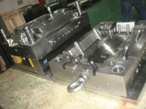
Liquid helped molding is a genuinely old cycle having filled in as a choice to injection molding for china precision plastic injection mold factory. Two varieties of a more current gas help measure with infusion decompression are appeared in Fig. 13.4 [7]. In the primary strategy, two shape parts 10 and 11 structure a form pit 12 into which the plastic dissolve will stream. The trim machine’s spout 13 has an inner center 16 with a sliding valve 19 that is impelled by packed gas on the other hand presented through gas lines 20 and 21 through three-way valves 22 and 23. Toward the start of the interaction, the plastic liquefy 24 is brought into the form pit through the machine spout 13; simultaneously, the sliding valve 19 is in a position which obstructs the gas bay cylinder 18 compacting the gas through line 21 decompressing the gas through line 20. After the form pit is somewhat filled, gas line 20 is compressed while gas line 21 is depressurized. This makes the sliding valve take on the situation as shown so that gas gulf tube 18 is opens and conveys compacted gas to the shape hole. When the gas has been injected, the sliding valve is then incited to forestall the undesired progression of the plastic dissolve. After the formed part cools, the launch of the shape makes the sprue break and the arrival of any packed gas to the surrounding climate.

A subsequent technique is additionally appeared in injection mold manufacturing china in which the opposite of injection pressure, injection decompression, is utilized to mold an empty part with a huge cavity. In this plan, the plastic liquefy streams into a cavity framed between two shape parts 30 and 32. While not appeared, these shape parts can have fine subtleties like supervisors that are full grown by the underlying filling of the depression with the polymer liquefy. The compacted gas is then infused into a thicker segment of the form cavity.

Simultaneously, the mold center 32 is withdrawn from its restricting mold half 30 to develop the cavity. Thusly, moldings with exceptionally huge interior holes (for instance, 50 mm) can be shaped while saving fine highlights on the outside surfaces of the formed part.

This article is from http://www.chinainjectionmold.com/
Turning Center

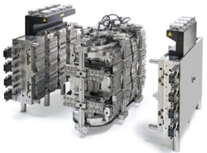
Folding centers are generally easy to fuse into shape plans when utilizing a bought gathering, and can be utilized for the framing of strings, dimples, windows, and other interior highlights. Be that as it may, one issue with folding centers is the development of witness lines on the inside of the shaped part where the center portions interface. Depending 0n the application necessities, these observer lines may disallow the utilization of the folding centers. In that capacity, various shape plans have been created with turning centers for the arrangement and demolding of inner strings. One plan is shown in oem/odm industrial injection moulding design factory for a 64 depression form for the creation of strung covers [13]. The shape configuration incorporates cavities 16 that are framed by coordinating arrangements of hole embeds 10 and center supplements 15. The rear of each center incorporates a vital help 17, which is mounted upon a shaft 18 that reaches out from a coarsely strung helix 19. The helix is pivotally situated between the back brace plate 21 and the help plate 23, and radially upheld by course 20 and 26.

1

Devotee pins 30 have been fitted to the incited plate 29 that connect with the strings of the helix 19. Since these pins can’t pivot, the activation of the plate 29 will cause the revolution of the helix 19, and the resulting turn of the strung centers 15. Concerning plan, a coarsely strung helix is fundamental since the force and wear will increment considerably as the pitch diminishes. All things considered, the necessary length of the helix is identified with the erosion between the helix and the supporter, just as the quantity of pivots in the embellishment application.

Another shape plan for turning centers is appeared in the arrangement perspective on mould manufacturers china. In this form plan, a focal sun gear 84 at the same time activates different planetary pinion wheels 86, which thus drive shafts 88. The center supplements are not appeared in plastic molding services china, however are keyed to the drive shafts through spaces 66. There are numerous potential plans to turn the sub stuff 84. In this plan, a pinion 42 is connected to a shaft 74 which closes at a slope gear 76. This slope gear 76 lattices with another slant gear 78 that is bolted to the focal sun gear 84. In activity, the form opening stroke causes

■the rack 44 to draw in the pinion 42,

■the pinion 42 to pivot the shaft 74,

■ the shaft 74 to pivot the incline gear 76,

■the slope gear 76 to pivot the incline gear 78,

■the slant gear 78 to turn the sun gear 84,

■ the sun stuff to pivot the planetary cog wheels 86,

■ the planetary cog wheels 86 to turn the shaft 88, and

■the shaft 88 to pivot the centers keyed to opening 66.

With either plan procedure, the high-precision molds made in china ought to guarantee that the part calculation is intended to forestall the turn of the shaped part with the pivoting center. Now and again, the sprinter and door may give adequate solidarity to forestall the formed part’s revolution. In different cases, nonetheless, this methodology is insufficient since the discharge powers will in general shift with the material properties, preparing conditions, and surface completion as examined before in china mould design services. Therefore, the mold configuration may utilize some little undermines or other nonasymmetric highlights to forestall the part revolution.

This article is from http://www.chinainjectionmold.com/

Split Cavity

One split hole form configuration is appeared in china high precision mold manufacturer for the trim of bowling pins. The shape incorporates a top brace plate 14, a cavity retainer plate 16, and a help plate 12, among others. The split depression is framed by two moving pit embeds 23 and 24 that mate with the tapered bore 21 in the cavity retainer plate 16 when the form is shut. Four lengthened point pins 30 are secured in the top clip plate and stretch out through the cavity embeds 23 and 24. Every pit embed is attached to two gibs 28 that can cross in slideways 26.

At the point when the shape opens, the help plate 12 is moved away from the cavity retainer plate 16. Since the point pins 30 are fixed and slanted comparative with the form opening bearing, the pit embeds 23 and 24 are compelled to move away from one another through a cam activity. At last, an adequate leeway is delivered between the shaped section 66 and the cavity side dividers 44 with the goal that the formed item might be taken out.

There are a couple of fascinating things to note with respect to this specific split pit shape plan. To start with, there is a lot of shape cheek gave in the hole retainer plate 16. The thickness of the cheek is needed to stay away from unreasonable shear pressure and diversion of the depression side dividers 44. It is seen that the thickness of the cheek is around equivalent to the profundity of the shape depression, as proposed by the investigation of china precision injection plastic parts factory. Second, wear can be an issue in this form configuration because of the enormous mass of the supplements, the length of movement, and the high number of trim cycles. Hence, the gibs should be determined to incorporate lubricity and be effortlessly supplanted when important. Likewise, wear plates should be joined between the help plate 12 and the cavity embeds 23 and 24. Third, interior cooling of the center is given using a huge bubbler 75 with coolant delta 74 and source 76.

Split depression molds have been intended for a long while, and this plan was not chosen exclusively because of its consolidation of a split hole plan. Another fascinating component of the plan is the forward incitation of the center pin 50 during the filling and pressing stages to give infusion pressure forming. This activation is expected to make up for the exceptionally high volumetric shrinkage during the hardening of the thick side dividers 54 of the formed part. Accordingly, the shape configuration incorporates a heading 46 that bolsters the shoulder 65 of the center pin. Since the shaped section 66 will in general therapist onto the center pin 50, the center pin should be withdrawn after the form is opened as appeared in china injection mold factory to deliver the shaped part.

The distance across of financially accessible folding centers goes from 13 to 90 mm, with a breakdown of around 6 % of the center measurement. While their breakdown isn’t close to as much as the plan of precision molds factory, these standard segments uphold completely programmed trim of little highlights, for example, inner strings for shaped terminations. This article is from http://www.chinainjectionmold.com/