Klarm Mould Offers Large Size Mold China

The mold plan of liquid helped shape needs to change significantly from that of injection and co-injection molds. Specifically, the form planner needs to think about the area for the injection of the gas or water. As exhibited in mould manufacturers china both the spout and pit are normal areas. As significantly, the shape planner should cautiously plan the mold to have suitable stream channels to deliberately coordinate the gas or water through the shape cavity. In most shape plans, the cavity divider thickness is made as uniform as conceivable to stay away from nonuniform cooling and shrinkage. Notwithstanding, such a form configuration won’t prompt a successful shape for liquid help. The explanation is that the gas or water will pervade or”finger” in arbitrary bearings through a consistently thick mold pit, subsequently debilitating the trim without fundamentally diminishing the part weight. Thusly, thick stream diverts as demonstrated in Fig. 13.5 are regularly added to the shape hole to coordinate the gas or water through the form pit. Every one of the gas channels will show some anomaly paying little heed to the extent of infiltration. By and large, it is attractive to build up a gas channel to give as uniform a formed divider as could really be expected while giving the important liquid stream and part solidness. Thus, the upper right gas direct in Fig.13.5 is least liked. Since the other stream channels are cored out by the liquid, the cooling and shrinkage is made moderately uniform without broadened process duration.

Water help shaping appears to have gotten expanded interest recently. Contrasted with gas help, water help gives at any rate three key advantages. In the first place, water has an exceptionally high explicit warmth thus can be injected to decrease the process duration contrasted and gas help shaping application. Truth be told, in some water help shaping applications, the stream channels are planned with deltas and outlets, to such an extent that the water can be coursed inside the molded part and accordingly enormously lessen heat move through heat convection. Second, water is in-compressible contrasted with gas, and S0 can be utilized by china mould design services to give higher soften pressures in the pit with less energy and hazard than gas. Third, it has been shown that water help gives more uniform and smooth surface in within the molded parts.

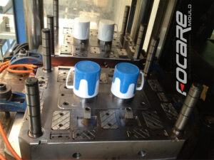
With these benefits, be that as it may, water help brings two huge impediments. To start with, the water should be eliminated from the inside of the molded parts; different plans from plastic injection mold manufacturers china have been created to eliminate the water inward to the trim before the form opening. Second, the utilization of water in the trim climate will in general expand dampness and consumption, so an erosion safe form material, for example, SS420 is suggested.

This is from http://www.chinainjectionmold.com

Klarm Mould Provides molds & tooling services china

Gas and water are the two liquids, so the two gas help embellishment and water help trim can be considered as kinds of liquid helped shaping cycles. Since these helping liquids are injected within a first material, all liquid help molding cycles can be viewed as a sort of co-injection molding interaction. Contrasted with conventional co-injection with polymer dissolves, liquid helped forming has two unmistakable contrasts for china precision injection plastic parts factory.

To start with, the second injected liquid (like nitrogen or water) has a low consistency contrasted with the recently injected polymer soften. This low thickness accommodates an exceptionally low pressing factor drop along the stream way, and consequently gives magnificent pressing factor transmission for pressing out the recently injected polymer dissolve. Second, the helping liquid is subsequently taken out from the formed part in order to burrow out within the shaped part. With cautious form plan, liquid helped moldings can have expanded strength, lighter weight, and diminished process duration contrasted with traditional or co-injected molds.

Liquid helped molding is a genuinely old cycle having filled in as a choice to injection molding for china precision plastic injection mold factory. Two varieties of a more current gas help measure with infusion decompression are appeared in Fig. 13.4 [7]. In the primary strategy, two shape parts 10 and 11 structure a form pit 12 into which the plastic dissolve will stream. The trim machine’s spout 13 has an inner center 16 with a sliding valve 19 that is impelled by packed gas on the other hand presented through gas lines 20 and 21 through three-way valves 22 and 23. Toward the start of the interaction, the plastic liquefy 24 is brought into the form pit through the machine spout 13; simultaneously, the sliding valve 19 is in a position which obstructs the gas bay cylinder 18 compacting the gas through line 21 decompressing the gas through line 20. After the form pit is somewhat filled, gas line 20 is compressed while gas line 21 is depressurized. This makes the sliding valve take on the situation as shown so that gas gulf tube 18 is opens and conveys compacted gas to the shape hole. When the gas has been injected, the sliding valve is then incited to forestall the undesired progression of the plastic dissolve. After the formed part cools, the launch of the shape makes the sprue break and the arrival of any packed gas to the surrounding climate.

A subsequent technique is additionally appeared in injection mold manufacturing china in which the opposite of injection pressure, injection decompression, is utilized to mold an empty part with a huge cavity. In this plan, the plastic liquefy streams into a cavity framed between two shape parts 30 and 32. While not appeared, these shape parts can have fine subtleties like supervisors that are full grown by the underlying filling of the depression with the polymer liquefy. The compacted gas is then infused into a thicker segment of the form cavity.

Simultaneously, the mold center 32 is withdrawn from its restricting mold half 30 to develop the cavity. Thusly, moldings with exceptionally huge interior holes (for instance, 50 mm) can be shaped while saving fine highlights on the outside surfaces of the formed part.

This article is from http://www.chinainjectionmold.com/

Klarm Mould Perfect Molding Design

For china industrial injection mold manufacturers, their end goal of structural design , a center can be viewed as shallow when the tallness of the center is not exactly both the width and length of the center. Shallow centers, for example, for the bezel form, won’t be exposed to exorbitant pressure or redirection brought about by the use of the soften strain to the side dividers of the center. Thusly, shallow centers can be planned by the recently depicted investigation for form plates. Profound centers need further thought of pressure and avoidance as next examined.

The vertical redirection of centers because of pressure by the soften can be displayed as recently examined in Section 12.2.1, however with the compressive powers and cross-sectional regions proper for the center as demonstrated as a visual cue.

The underlying model of profound centers is additionally confounded since profound centers can twist because of the utilization of parallel powers from the liquefy pressure against their sides. Center twisting might be a critical issue when centers are thin and have a low firmness related with their cross-sectional region, es pecially when the centers are dug out to accommodate shape coolant. Investigation and plan of the center should guarantee that the potential center redirection isn’t inordinate and that the compressive anxieties around the border of the center are adequate, These two concerns are next tended to.

In the injection moulding services, it might create the impression that the cooling embed in the plan of Fig. 12.25 will completely uphold the center addition. While this presumption may demonstrate satisfactory, a more vigorous plan is given by expecting that the cooling embed offers no help. There are two explanations behind making this supposition. To start with, the external surfaces of the cooling addition may not firmly fit the inward surfaces of the center supplement. Any leeway or hole more noteworthy than the diversion of the center will totally forestall the cooling embed from supporting the center. Second, the cooling addition might be produced using an unexpected material in comparison to the center supplement, like aluminum. At that point, the cooling supplement probably won’t withstand the burdens im presented while sup porting the center addition.

The absolute diversion of the top surface of the center can be assessed by superimposing the pressure of the side dividers with the twisting of the top surface. While the compressive pressure dissemination in the side dividers of the center isn’t completely uniform, the normal pressure is around the applied power from the top isolated by the cross-sectional region of the side dividers.

China injection mold maker knows it well that bending from the edge of the top surface to the focal point of the center can be determined utilizing pillar or plate bowing conditions of Section 12.2.2 and added to the relocation because of pressure to appraise the absolute vertical redirection.

This article is from http://www.chinainjectionmold.com/

Klarm Mold Offers Injection Moulding Services China

In mold plates for plastic injection moulded components china, stress focuses [7-10] will occur any place material has been eliminated between the shape pit and the supporting plates. Stress fixations are particularly basic in injection molds because of the establishment of water lines and ejector openings just as the sharp corners that can be given electric release machining (EDM). The subsequent pressure circulation about the opening will be like that appeared in Fig. 12.23. In this model, an opening has been given in a mold plate a ways off of 1.5 occasions the opening’s measurement; a two-dimensional, plane strain model [11] was utilized with a fixed back surface and evenness conditions on the left and right sides. A pressing factor of 10 MPa has been applied to the top surface. The subsequent most extreme von Mises pressure is 29.5 MPa, which relates to a pressure focus factor of around 3.

As the opening is moved further away from the shape depression, the pressure focus is decreased. To assess the pressure focus factor, a progression of limited component analyses were performed with shifting mold calculations. The profundity of the opening, from the top surface to the opening center line, fluctuated from 0.6 to 4 while the even pitch between cooling lines was shifted from 2 to4 to 8. Fig. 12.24 plots the pressure focus as an element of the quantity of opening measurements from the depression surface to the center line of the opening. Fig. 1 2.24 likewise incorporates pressure focus information for various pitches, and demonstrates that cooling line pitch isn’t as critical a determinant of stress fixation contrasted with the opening profundity. A model of the pressure focus factor, K, was fit to the information for a pitch of four widths, giving a model to the pressure fixation.

Besides, it is seen that a pressure grouping of 2.75 will happen in any event, when an opening is situated a long way from the cavity surface. Injection moulding services china come to know that this clarifies why numerous molds create breaks radiating from the waterlines in trim applications with high soften pressures, in any event, when the cooling lines are situated a long way from the pit surface.

Cooling lines appear to cause more critical issues than ejector openings practically speaking. The explanation is that cooling lines consume, causing inward tiny pressure fixations. Breaks at that point radiating from cooling lines will at last release and cause quality issues with the moldings. Therefore, molding applications with high soften pressing factors ought to be built of materials with high perseverance stresses like A6, D2, or H13.

By correlation, breaks exuding from ejector openings may not at any point cause a disastrous disappointment. The explanation is that the deformity of the ejector opening under burden can make the plate around opening be upheld by the ejector, in this manner lessening the pressure around the opening. In that capacity, breaks proliferating from ejector openings will arrive at a basic length so, all in all the flexible distortion of the center addition onto the ejector forestalls further break spread.

This article is from http://www.chinainjectionmold.com/

Klarm Mould Promotes injection moulder services

Guangzhou Klarm Mould Limited is one precision plastic injection mold factory in South China, offering injection molder services. Below shows some techniques utilized during the design for injection molding china.

Plate redirection can be diminished essentially using support columns situated between the back clip plate and the help plate. All in all, uphold columns are best positioned straightforwardly under the parts of the form pit that produce huge power. By offering direct help of the shape plates, shear stresses and bowing near the help column are altogether decreased.

An average plan is given by china mould manufacturer. In this plan, a freedom is given through the ejector plate and the ejector retainer plate. The help column is then found utilizing a dowel that mates the focal point of the help column to an opening is in the back brace plate. Since the help plate is made sure about to the back clip plate with attachment head cap screws, the help column is completely made sure about upon form get together.

Lamentably, the area of help columns can struggle with different segments including the ejector pins and the ejector take out rod(s). Consequently, various designs and sizes of help columns ought to be dissected. In the event that form diversion is a basic issue, at that point the ejector format can be acclimated to give space to a few enormous help columns at ideal areas. Three potential help column areas are given in Fig. 12.14. At left, two more modest help columns are situated external the ejector sharp edges; the help columns are decently equally separated concerning the range of the bezel. Notwithstanding, the help columns can’t be set straightforwardly under the bezel face without adjusting the ejector format.

Another plan may call for one enormous help column at the focal point of the form in order to keep away from obstruction with the ejector pin design. In any case, this help column may not incredibly lessen the redirection of the form plates since critical plate twisting can at present 0CCUr because of the stacking on the left and right sides of the trim.

Moreover, this plan could strife with the utilization of a halfway found ejector pole from the embellishment machine, which is very normal. As another other option, the design at right of oem/odm injection mold factory utilization a solitary help mainstay of middle size. This plan needs less help columns than the principal configuration, however has a bigger range between the help column and the ejector rail thus can permit some redirection because of plate bowing.

The number, area, and size of the help columns ought to be broke down. One of the complexities of the investigation is that the help columns are primary individuals from limited width and firmness. This implies that the help columns will avoid under the compressive burden. The center supplement and backing plate will likewise avoid with the help column. Moreover, the center addition and the help plate will show bowing between the help column and the ejector rail. To assess the absolute plate avoidance, superposition is utilized to add the redirection because of pressure and twisting.

To play out the investigation, the powers across the form should be changed over to a bunch of burden cases that is reasonable for manual examination. Figure 12.16 gives the transformation from the dissolve pressure forced on the outside of the shape hole to pressure and bowing burden cases. The complete power, F, is the vital of the soften pressure across the length and width of the depression. To gauge the bowing; this power is broken into halves applied at the focal point of the range between the help column and the ejector rail. A power equilibrium would then be able to be applied to decide the powers that should be conveyed by the help pillar(s) and the ejector rails.

Klarm Mould Help your Mold Minimize

Klarm Mould, an oem/odm industrial mold design factory, can help for your mold design and minimizing. Here it shows plots the redirection of the mold and platens for the pressure dissemination. It is seen that the most extreme shape redirection happens at the focal point of the form cavity, with the center surface diverting 0.24 mm to one side and the hole surface avoiding 0.12 mm to one side. Accordingly, the liquefy pressure in the shape pit makes the surfaces separate by a sum of 0.36 mm (0.014 in).

This avoidance will cause any close by separating lines to open a comparable sum. Since this sum is a lot more noteworthy than the vent thickness (normally on the request for 0.02 mm), a lot of glimmering is normal. The form configuration should be improved to diminish this redirection.

The plotted shapes demonstrate that there is platen avoidance too. Shape fashioners and decays normally expect platens to be level and vastly unbending. While outside the extent of this book, platen diversion can be a critical issue. In oem/odm automatives injection molding design factory, the redirection of the fixed platen is around 0.04 mm, generally double that of the moving platen. The explanation is that the shape’s ejector lodging will in general exchange powers nearer to the sides of the moving platen so there is less applied burden and diversion in the focal point of this platen contrasted with the avoidance of the fixed platen.

The mold architect from china industrial injection moulding manufacturers can examine diverse shape materials and plans to decrease the form pressure and redirection. A survey of the material properties in Appendix B will uncover that harder materials, (for example, H13) can withstand a lot higher burdens than gentler materials, (for example, 1045 or QC7). Notwithstanding, the shape originator should know that all prepares have almost a similar flexible modulus, around 200 GPa. Therefore, the shape fashioner can’t change the avoidance by steel choice, but instead should depend on changing the calculation of the mold.

The least difficult strategy to diminish diversion is to expand the thickness of plates. As later investigation will show, this methodology is powerful since the solidness of the shape plates is identified with the block of the plate thickness. All things being equal, the rehashed utilization of huge and thick plates can bring about an excessively substantial and costly mold with a stack stature that restricts the accessibility of embellishment machines. Thus, the mold creator should try to limit the size of the form through fitting examination and cautious detail of plate thicknesses and backing structures, for example, uphold pillar and interlocks.

In mold plan, the term”plate” alludes to a kaleidoscopic or rectangular primary part with a length and width regularly more prominent than the thickness. The “face”of the plate for the most part alludes to the top and base surfaces of the plate that range the width and length headings. The”sides” of the plate allude to the four external surfaces of the plate that cross the thickness bearing. Shape plates are generally accessible from various providers in an assortment of sizes and materials. Plates can be furnished larger than average with a slight (1 mm) stock stipend, or finish ground to resilience on the request for +0.02 mm. This article is from http://www.chinainjectionmold.com


Molding Pressure Control

The pressure strain conduct of two normal shape metals, P20 and aluminum QC7, are plotted in oem/odm industrial mold factory. P20 has a lot higher modulus than QC7, implying that it will display less strain and misshapening given an applied burden or stress. The yield pressure is where the material withdraws from its straight conduct. The yield pressure is likewise the pressure at which the material plastically disfigures, implying that the segments with a higher pressure won’t re-visitation of their unique shape after the heap is taken out. When the material surpasses the yield pressure, it can keep on conveying load up to a definitive pressure, after which it flops totally.

All shape plans should be designed to work at stresses lower than the yield pressure. Regarding determining a wellbeing component to relate the yield pressure as far as possible pressure, there are two basic methodologies. One methodology is to just set the cutoff stress equivalent to the yield pressure, however then accept a most dire outcome imaginable concerning the heap condition. For instance, a form fashioner working with P20 could accept a cutoff stress equivalent to the yield pressure of 830 MPa. To guarantee the form doesn’t yield under burden, the shape fashioner should then perform examination accepting the most noteworthy liquefy pressures that the form could actually be required to see, maybe 200 MPa.

Another methodology for precision molds made in china is to set the breaking point pressure equivalent to the yield pressure partitioned by a factor of security: σlimmit=σyield/f, where fis the factor of wellbeing, whose worth is identified with the degree of vulnerability and the expense of a possible disappointment, Typical qualities range from 1.5 for non basic form segments to 6.0 for raise rings.When a factor of security is utilized, the shape fashioner ought to apply the normal dissolve pressure for the shape, maybe 100 MPa.

To try not to over-plan the mold, the mold designer of oem/odm industrial mold design factory ought not mutually apply a factor of security with the most dire outcome imaginable. While the form creator may expect that a plan dependent on the yield pressure with a moderate factor of security would be hearty, this methodology may bring about molds that fizzle after countless embellishment cycles. The explanation is that the contin ued cycling of bracing burdens and liquefy pressure in the shape pit causes cyclic anxieties as appeared in high precision plastic making mould suppliers china. Each pressure cycle permits little breaks in the form to open and close, causing a couple of more gems at the break tip to fall flat. Throughout the span of thousands of embellishment cycles, these breaks will develop and engender through the form like a wedge driven by a mallet. When the break arrives at a basic size, the pressure focuses around the break will make the shape flop in any event, when the form was appropriately planned with a cutoff stress determined well underneath the yield pressure. This disappointment mode is by and large alluded to as weakness. This article is from http://www.chinainjectionmold.com/

Turning Center

Folding centers are generally easy to fuse into shape plans when utilizing a bought gathering, and can be utilized for the framing of strings, dimples, windows, and other interior highlights. Be that as it may, one issue with folding centers is the development of witness lines on the inside of the shaped part where the center portions interface. Depending 0n the application necessities, these observer lines may disallow the utilization of the folding centers. In that capacity, various shape plans have been created with turning centers for the arrangement and demolding of inner strings. One plan is shown in oem/odm industrial injection moulding design factory for a 64 depression form for the creation of strung covers [13]. The shape configuration incorporates cavities 16 that are framed by coordinating arrangements of hole embeds 10 and center supplements 15. The rear of each center incorporates a vital help 17, which is mounted upon a shaft 18 that reaches out from a coarsely strung helix 19. The helix is pivotally situated between the back brace plate 21 and the help plate 23, and radially upheld by course 20 and 26.

1

Devotee pins 30 have been fitted to the incited plate 29 that connect with the strings of the helix 19. Since these pins can’t pivot, the activation of the plate 29 will cause the revolution of the helix 19, and the resulting turn of the strung centers 15. Concerning plan, a coarsely strung helix is fundamental since the force and wear will increment considerably as the pitch diminishes. All things considered, the necessary length of the helix is identified with the erosion between the helix and the supporter, just as the quantity of pivots in the embellishment application.

Another shape plan for turning centers is appeared in the arrangement perspective on mould manufacturers china. In this form plan, a focal sun gear 84 at the same time activates different planetary pinion wheels 86, which thus drive shafts 88. The center supplements are not appeared in plastic molding services china, however are keyed to the drive shafts through spaces 66. There are numerous potential plans to turn the sub stuff 84. In this plan, a pinion 42 is connected to a shaft 74 which closes at a slope gear 76. This slope gear 76 lattices with another slant gear 78 that is bolted to the focal sun gear 84. In activity, the form opening stroke causes

■the rack 44 to draw in the pinion 42,

■the pinion 42 to pivot the shaft 74,

■ the shaft 74 to pivot the incline gear 76,

■the slope gear 76 to pivot the incline gear 78,

■the slant gear 78 to turn the sun gear 84,

■ the sun stuff to pivot the planetary cog wheels 86,

■ the planetary cog wheels 86 to turn the shaft 88, and

■the shaft 88 to pivot the centers keyed to opening 66.

With either plan procedure, the high-precision molds made in china ought to guarantee that the part calculation is intended to forestall the turn of the shaped part with the pivoting center. Now and again, the sprinter and door may give adequate solidarity to forestall the formed part’s revolution. In different cases, nonetheless, this methodology is insufficient since the discharge powers will in general shift with the material properties, preparing conditions, and surface completion as examined before in china mould design services. Therefore, the mold configuration may utilize some little undermines or other nonasymmetric highlights to forestall the part revolution.

This article is from http://www.chinainjectionmold.com/

Split Cavity

One split hole form configuration is appeared in china high precision mold manufacturer for the trim of bowling pins. The shape incorporates a top brace plate 14, a cavity retainer plate 16, and a help plate 12, among others. The split depression is framed by two moving pit embeds 23 and 24 that mate with the tapered bore 21 in the cavity retainer plate 16 when the form is shut. Four lengthened point pins 30 are secured in the top clip plate and stretch out through the cavity embeds 23 and 24. Every pit embed is attached to two gibs 28 that can cross in slideways 26.

At the point when the shape opens, the help plate 12 is moved away from the cavity retainer plate 16. Since the point pins 30 are fixed and slanted comparative with the form opening bearing, the pit embeds 23 and 24 are compelled to move away from one another through a cam activity. At last, an adequate leeway is delivered between the shaped section 66 and the cavity side dividers 44 with the goal that the formed item might be taken out.

There are a couple of fascinating things to note with respect to this specific split pit shape plan. To start with, there is a lot of shape cheek gave in the hole retainer plate 16. The thickness of the cheek is needed to stay away from unreasonable shear pressure and diversion of the depression side dividers 44. It is seen that the thickness of the cheek is around equivalent to the profundity of the shape depression, as proposed by the investigation of china precision injection plastic parts factory. Second, wear can be an issue in this form configuration because of the enormous mass of the supplements, the length of movement, and the high number of trim cycles. Hence, the gibs should be determined to incorporate lubricity and be effortlessly supplanted when important. Likewise, wear plates should be joined between the help plate 12 and the cavity embeds 23 and 24. Third, interior cooling of the center is given using a huge bubbler 75 with coolant delta 74 and source 76.

Split depression molds have been intended for a long while, and this plan was not chosen exclusively because of its consolidation of a split hole plan. Another fascinating component of the plan is the forward incitation of the center pin 50 during the filling and pressing stages to give infusion pressure forming. This activation is expected to make up for the exceptionally high volumetric shrinkage during the hardening of the thick side dividers 54 of the formed part. Accordingly, the shape configuration incorporates a heading 46 that bolsters the shoulder 65 of the center pin. Since the shaped section 66 will in general therapist onto the center pin 50, the center pin should be withdrawn after the form is opened as appeared in china injection mold factory to deliver the shaped part.

The distance across of financially accessible folding centers goes from 13 to 90 mm, with a breakdown of around 6 % of the center measurement. While their breakdown isn’t close to as much as the plan of precision molds factory, these standard segments uphold completely programmed trim of little highlights, for example, inner strings for shaped terminations. This article is from http://www.chinainjectionmold.com/

Slides

To give as protected and proficient a shape as could reasonably be expected, the form creator ought to indicate the utilization of limit changes to affirm that the moving center is in its forward or withdrawn position, These position signs can be utilized by the embellishment machine to guarantee that the moving centers are appropriately situated to not harm the formed parts or the infusion form during mold opening or part discharge. Moreover, the form architect ought to endeavor to plan the moving center with the end goal that the shape opening or part discharge doesn’t harm the shape if the moving center is inappropriately situated. Consider, for instance, the plan appeared in china high precision mold supplier. On the off chance that the shape is opened and the part shot out with the pushing center in its ahead position, all things considered, the plastic part will be sheared off at the essential rib by the incitation of the close by ejector sleeve and ejector edge. Clearly, this occasion is undesired and ought not happen for an appropriately set embellishment measure. Notwithstanding, such occasions do happen and decays enormously like a powerful form plan that can withstand discontinuous maltreatment without adjusting the ejector pins, cutting edges, sleeves, or moving centers.

Center pulls are very regular since they permit moving supplements to be activated in various ways, strokes, and times. In any case, center pulls require actuators, auxilliary control, and huge space. Therefore, form originators regularly like to utilize sliding centers that are incited by slanted point pins.

One such shape configuration is appeared in oem/odm industrial injection mold design factory. In this plan, a bronze gib is situated in the B plate to give a greased up sliding surface to the moving supplement. The center addition is furnished with a slanted can surface that mates with the point pin, As the form opens and shuts, the point pin draws in the sliding center, making the center move in and out. A retainer plate made sure about to the B plate keeps the sliding center from dropping out of the gib.

The point by point configuration is appeared in china custom mold components and warrants further conversation. The point pin is situated using a point pin embed, which has a level surface to arrange the point pin toward the sliding activity. While there are numerous approaches to plan a slide for side activity, the point pin embed is held between the center addition and a heel block by attachment head cap fastens this plan. On the moving side of the shape, the bronze gib is situated with dowels and affixed with cap sinks to a pocket cut the B plate and center supplement. The gib gives a keyway into which directs the sliding center. The sliding center itself is fundamentally the same as that recently appeared in oem/odm industrial injection moulding factory.

In activity, the clasping of the shape makes two powers be forced on the sliding center. To start with, the calculated surface on the heel block contacts the calculated surface on the slide to constrain the slide along the side against the center addition; this parallel power withstands the dissolve pressure and forestalls blazing of the ribs, supervisors, and window. Second, the pit embed contacts the top surface of the slide, which gives a descending clasping power to forestall redirection and glimmering around the splitting line of the trim. It should be noticed that the point pin doesn’t give the sidelong power and isn’t exposed to huge pressure in this plan. All around planned clearances, resiliences, and fits are pivotal to the capacity and life span of the sliding center.

This article is from http://www.chinainjectionmold.com