Klarm Mould Help your Mold Minimize

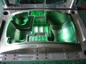
Klarm Mould, an oem/odm industrial mold design factory, can help for your mold design and minimizing. Here it shows plots the redirection of the mold and platens for the pressure dissemination. It is seen that the most extreme shape redirection happens at the focal point of the form cavity, with the center surface diverting 0.24 mm to one side and the hole surface avoiding 0.12 mm to one side. Accordingly, the liquefy pressure in the shape pit makes the surfaces separate by a sum of 0.36 mm (0.014 in).

This avoidance will cause any close by separating lines to open a comparable sum. Since this sum is a lot more noteworthy than the vent thickness (normally on the request for 0.02 mm), a lot of glimmering is normal. The form configuration should be improved to diminish this redirection.

The plotted shapes demonstrate that there is platen avoidance too. Shape fashioners and decays normally expect platens to be level and vastly unbending. While outside the extent of this book, platen diversion can be a critical issue. In oem/odm automatives injection molding design factory, the redirection of the fixed platen is around 0.04 mm, generally double that of the moving platen. The explanation is that the shape’s ejector lodging will in general exchange powers nearer to the sides of the moving platen so there is less applied burden and diversion in the focal point of this platen contrasted with the avoidance of the fixed platen.

The mold architect from china industrial injection moulding manufacturers can examine diverse shape materials and plans to decrease the form pressure and redirection. A survey of the material properties in Appendix B will uncover that harder materials, (for example, H13) can withstand a lot higher burdens than gentler materials, (for example, 1045 or QC7). Notwithstanding, the shape originator should know that all prepares have almost a similar flexible modulus, around 200 GPa. Therefore, the shape fashioner can’t change the avoidance by steel choice, but instead should depend on changing the calculation of the mold.

The least difficult strategy to diminish diversion is to expand the thickness of plates. As later investigation will show, this methodology is powerful since the solidness of the shape plates is identified with the block of the plate thickness. All things being equal, the rehashed utilization of huge and thick plates can bring about an excessively substantial and costly mold with a stack stature that restricts the accessibility of embellishment machines. Thus, the mold creator should try to limit the size of the form through fitting examination and cautious detail of plate thicknesses and backing structures, for example, uphold pillar and interlocks.

In mold plan, the term”plate” alludes to a kaleidoscopic or rectangular primary part with a length and width regularly more prominent than the thickness. The “face”of the plate for the most part alludes to the top and base surfaces of the plate that range the width and length headings. The”sides” of the plate allude to the four external surfaces of the plate that cross the thickness bearing. Shape plates are generally accessible from various providers in an assortment of sizes and materials. Plates can be furnished larger than average with a slight (1 mm) stock stipend, or finish ground to resilience on the request for +0.02 mm. This article is from http://www.chinainjectionmold.com

 

Two-Plate Molds

The formats of the various kinds of feed systems from high-precision mould manufactory and their going with segments are examined in more noteworthy detail.

The two-plate mold is so named in light of the fact that it comprises of two amassed areas that sandwich the dissolve; every 50% of the form can comprise of at least one mold plates. A segment of an isometric mold is given in Fig. 6.4, in which the concealing speaks to the movement of the polymer liquefy. During the embellishment cycle, the spout of the trim machine mates with the span of the sprue bushing. The polymer dissolve first streams down the sprue bushing, accordingly crossing the thickness of the top brace plate and A plate. The material at that point streams over the splitting plane through sprinters and entryways into at least one mold pits.

After the polymer is completely infused and set, the mold is opened at the splitting plane, which is situated between the An and the B plates. Regularly, the A portion of the mold stays fixed while the B half of the form is pulled away with the moldings and sprinter framework staying on the center. To encourage launch, a converse mold is normally given on a take out pin beneath the sprue to guarantee that the sprue and appended sprinter stays with the B half. After the form has opened adequately to eliminate the moldings, the ejector plate is pushed forward by the embellishment machine. The sprue take out pin pushes on the sprue, breaking the little undercut and shooting the sprue from the B side of the mold. Extra ejector pins and take out pins can be put down the length of long sprinters to encourage launch of the feed framework.

In the plan of the feed system of oem/odm automotives injection molding factory, the length of the sprue is controlled by the joined thicknesses of the top clip plate and the A plate. The lengths of the sprinters are controlled by the situation of the depressions and the format of the related sprinters. Given this format, the mold creator needs to determine the widths of the feed framework. When all is said in done, the distances across of the upstream sprinters are bigger than the measurements of the downstream sprinters, since the progression of the polymer soften branches at sprinter intersections and there will be a lesser stream rate through every one of the downstream sprinters.

While a two-hole two-plate mold is utilized to show form plan ideas, the gave examination can be applied to more perplexing feed framework formats. For instance, china injection molded parts factory gives a feed system plan to an eight-cavity family form, including two essential sprinters, four optional sprinters, and eight tertiary sprinters. On the off chance that the stream rate through the sprue was 100 cc/s, at that point the stream rate through every one of the essential, optional, and tertiary sprinters would separately be 50 cc/s, 25 cc/s, and 12.5 cc/s. On the off chance that the stream obstruction in the depressions differed generously, nonetheless, at that point the stream rate in the tertiary sprinters could fluctuate considerably during the form filling stage.

Likewise with the feed system configuration appeared in oem/odm industrial mold factory, the distance across of each downstream sprinter is littler than the upstream sprinter appeared in Fig. 6.6. There is one prominent special case: the width of the trim machine’s spout opening is ordinarily littler than the distance across of the sprue delta. The littler opening in the machine spout gives a highlight division between the molded sprue and the cemented plug in the spout of the trim machine. In the event that the spout opening were bigger than the sprue bay, at that point a solidified part of plastic in the spout behind the sprue bushing could make the sprue adhere to the A portion of the mold. At the point when such staying occurs oftentimes, the decay may decide to perform a”sprue break” by withdrawing the infusion unit of the embellishment machine from the machine spout preceding mold opening and part launch. This activity is bothersome since it adds multifaceted nature and fluctuation to the embellishment cycle, so the form planner ought to check as well as suggest the spout hole measurement properly.

This article is from http://www.chinainjectionmold.com/

Mold Processing Cost

The oem/odm automatives injection molding design factory gives assessments of the absolute material utilization for different sorts of feed frameworks. A chilly sprinter is straightforward and ease however brings about shaped plastic that must be either disposed of or reused. Using the reused plastic as regrind diminishes the waste however acquires some cost identified with the work and vitality of reusing. As later portrayed, hot sprinters can possibly altogether diminish material expenses however expend noteworthy material during fire up and s0 are less compelling in short runs. gives appraisals of the all out material utilization for different kinds of feed frameworks. A chilly sprinter is straightforward and minimal effort however brings about shaped plastic that must be either disposed of or reused. Using the reused plastic as regrind diminishes the waste however brings about some cost identified with the work and vitality of reusing. As later depicted, hot sprinters can possibly essentially lessen material expenses yet devour critical material during fire up and s0 are less successful in short runs.

The handling cost per part is an element of the quantity of shape pits, the process duration, tevcle, and the hourly pace of the macintosh hinery and work, Rmolding: The process duration is affected principally by the thickness of the part, hwall, and, less significantly, by the size of the part and the sort of feed framework. While the process duration will be all the more precisely assessed during the cooling framework structure, a sensible gauge is given by where the cycle proficiency, fevcle eiciencv, is an element of the kind of feed framework and cycle that is being worked by Table 3.4. While it is alluring to work a completely programmed shaping cell with a hot sprinter, many disintegrates keep on utilizing cold sprinter molds working in self-loader mode.

The hourly rate for the trim machine is fundamentally a component of the clip weight, which drives the size and cost of the machine. The accompanying model was created relating the brace weight and ability to the machine hourly rate:

where Fclamp is the cinch weight in metric tons (m Ton), and fmachine is a factor identifying with the capacity of the machine and the related work. This condition was determined utilizing distributed U.S. public hourly rate information [2] for twelve diverse measured trim machines extending from 20 to 3500 metric tons; the portrayed model has a coefficient of assurance, R2, equivalent to 0.979.

The hourly rate information of high precision plastic injection mould factory is additionally an element of the geographic area, machine and disintegrate costs, and different elements. To represent these differences, the machine ability factor, fmachine, is assessed by china mould-building maker. By and large, forming machines with cutting edge abilities and higher brace weight cost more to buy; and work, thus order a value premium. Machines with particular ability, (for example, different infusion units or extremely high infusion pressures/speeds) are more costly to buy thus moreover order a value premium for every hour of activity. The expense of all assistants ought to be added to the fitting machine coefficient. While cutting edge innovation can build the hourly pace of the trim cycle, it ought to give a net reserve funds by improving quality and decreasing the handling and materials costs.

The cinch weight required for trim will be investigated during the flling framework plan. In any case, the clip weight can be moderately assessed accepting a normal liquefy weight of 80 MPa(11,600 psi) applied to the extended zone, Aprojected, of the shape depressions. In the event that the extended territory is obscure, it very well may be assessed as the result of the part length and width. The cinch power in metric tons, t= 9800 N, is at that point.

This article is from http://www.chinainjectionmold.com/