Klarm Mould Help your Mold Minimize

Klarm Mould, an oem/odm industrial mold design factory, can help for your mold design and minimizing. Here it shows plots the redirection of the mold and platens for the pressure dissemination. It is seen that the most extreme shape redirection happens at the focal point of the form cavity, with the center surface diverting 0.24 mm to one side and the hole surface avoiding 0.12 mm to one side. Accordingly, the liquefy pressure in the shape pit makes the surfaces separate by a sum of 0.36 mm (0.014 in).

This avoidance will cause any close by separating lines to open a comparable sum. Since this sum is a lot more noteworthy than the vent thickness (normally on the request for 0.02 mm), a lot of glimmering is normal. The form configuration should be improved to diminish this redirection.

The plotted shapes demonstrate that there is platen avoidance too. Shape fashioners and decays normally expect platens to be level and vastly unbending. While outside the extent of this book, platen diversion can be a critical issue. In oem/odm automatives injection molding design factory, the redirection of the fixed platen is around 0.04 mm, generally double that of the moving platen. The explanation is that the shape’s ejector lodging will in general exchange powers nearer to the sides of the moving platen so there is less applied burden and diversion in the focal point of this platen contrasted with the avoidance of the fixed platen.

The mold architect from china industrial injection moulding manufacturers can examine diverse shape materials and plans to decrease the form pressure and redirection. A survey of the material properties in Appendix B will uncover that harder materials, (for example, H13) can withstand a lot higher burdens than gentler materials, (for example, 1045 or QC7). Notwithstanding, the shape originator should know that all prepares have almost a similar flexible modulus, around 200 GPa. Therefore, the shape fashioner can’t change the avoidance by steel choice, but instead should depend on changing the calculation of the mold.

The least difficult strategy to diminish diversion is to expand the thickness of plates. As later investigation will show, this methodology is powerful since the solidness of the shape plates is identified with the block of the plate thickness. All things being equal, the rehashed utilization of huge and thick plates can bring about an excessively substantial and costly mold with a stack stature that restricts the accessibility of embellishment machines. Thus, the mold creator should try to limit the size of the form through fitting examination and cautious detail of plate thicknesses and backing structures, for example, uphold pillar and interlocks.
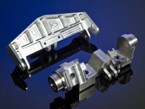
In mold plan, the term”plate” alludes to a kaleidoscopic or rectangular primary part with a length and width regularly more prominent than the thickness. The “face”of the plate for the most part alludes to the top and base surfaces of the plate that range the width and length headings. The”sides” of the plate allude to the four external surfaces of the plate that cross the thickness bearing. Shape plates are generally accessible from various providers in an assortment of sizes and materials. Plates can be furnished larger than average with a slight (1 mm) stock stipend, or finish ground to resilience on the request for +0.02 mm. This article is from http://www.chinainjectionmold.com

 

Shrinkage Range

Before making any last suggestions, it is helpful for injection mold company china to survey the likely mistake on the shrinkage gauge. The main blunders in the shrinkage expectations will probably come from the accepted soften weights and temperatures. Consequently, it is valuable to appraise the most extraordinary yet reasonable cutoff points for the weight and temperature to give a lower and maximum cutoff for the shrinkage:

■The lower limit for shrinkage will relate to a pressing stage with a long term and high dissolve pressure. The most extreme term relates to the time at which the plastic soften stops to stream once it Cools to the no stream temperature.

The gauge for the most noteworthy pressing weight is hard to anticipate, since it is represented by the decay’s cycle settings, particulars of the embellishment machine, and so forth A useful maximum breaking point for the pressing weight might be the more noteworthy of 120 % of the infusion weight or 100 MPa.

■The maximum cutoff for shrinkage will relate to a pressing stage with a brief span and low dissolve pressures. The decreased length will make the weight in the cavity completely rot before the plastic dissolve has adequately cooled, along these lines causing unreasonable volumetric shrinkage. Thusly, the most extreme shrinkage might be assessed by assessing the volumetric shrinkage at a low pressing weight (equivalent to the lesser of 40% of the infusion weight or 30 MPa) and a high dissolve temperature (equivalent, maybe, to the temperature somewhere between the no-stream temperature and the liquefy temperature).

Gauge the base and greatest shrinkage for the PC bezel in oem/odm medical injection moulding design factory. To ascertain the base shrinkage, expect that the dissolve temperature and weight toward the finish of pressing are 132°C and 100 MPa, individually. The particular volume toward the finish of packingis 9.50 .10-4 kg/m3, which brings about an expansion in the general volumetric shrinkage to 1.007. The straight shrinkage is assessed to be – 0.2 %. As such, so much material has been stuffed into the hole that the material will extend as opposed to contract once the part is launched out from the form! While this is a fascinating finding and happens infrequently, molds are not typically planned or worked with the aim of acquiring zero or negative shrinkage. The explanation is that some shrinkage is attractive so the plastic trim will pull away from the dividers of the depression and onto the center so the embellishment can be shot out. Negative shrinkage compares to”over packing”of the plastic in the shape depression. In an over pack circumstance, the material remaining parts compacted after shape opening, with the end goal that it may not be conceivable to deliver the part from hole subtleties, for example, ribs and managers.

To figure the most extreme shrinkage, china industrial injection mold suppliers accept that the dissolve temperature and weight toward the finish of pressing are 185°C and 30 MPa, individually. The particular volume toward the finish of pressing is 10.14. 10-3 kg/m3, which brings about a reduction in the general volumetric shrinkage to 0.943. The direct shrinkage is assessed from Eq.10.13 to be 1.9%, which is essentially higher than the recently assessed shrinkage of 0.3%. For this situation, the pressing stage has given lacking material to remunerate to the volumetric shrinkage in the shape hole. The mold designer from high precision plastic injection mould manufacturers ought to propose an all-encompassing pressing stage with higher pressing weights to maintain a strategic distance from abundance shrinkage. This article is from http://www.chinainjectionmold.com/


Mold Design Issues

For hot runner mold plans of high precision mould manufactory, the form planner should check the home season of the polymer liquefy in the hot runner to guarantee that the plastic won’t corrupt. The habitation time is straightforwardly identified with the quantity of goes needed to turn over the polymer soften in the hot runner system.

In the event that the volume of the hot runner is huge contrasted with the volume of the form holes, at that point many trim cycles might be needed to drive new material through the feed system. The quantity of turns doesn’t speak to the genuine number of embellishment cycles needed to cleanse the hot runner of the old gum, but instead the base number of trim cycles before a generous measure of the new gum is conveyed to the form holes.

A high number of turns is unfortunate for embellishment applications in which the shade of the pitch is oftentimes changed. To encourage continuous shading changes, mold creators ought to streamline the feed system measurements and downplay the quantity of turns. In the event that the quantity of turns is not exactly or near one, at that point the utilization of the hot runner system is probably not going to obstruct shading changes comparative with the shading change issues related with cleansing the injection unit of the embellishment machine from china molds produce services suppliers.

In the event that the quantity of turns is huge, on the request for at least 10, at that point cleansing the hot runner may turn into an extremely noteworthy issue with hundreds (or thousands) of embellishment cycles needed to totally cleanse low-consistency pitches. A high number of turns is additionally bothersome for trim applications with gums that have short permissible home occasions. The living arrangement season of material in the hot runner system is roughly.

This living arrangement time is estimated, since material moves through the hot runner system at different rates; the polymer liquefy close to the dividers and in dead spots of the hot runner can have any longer habitation times than those anticipated by high precision plastic injection mould manufacturers.

Moreover, the mold fashioner ought to recollect that the material streaming into the hot runner system has just lived in the barrel of the embellishment machine for a lot of time. In like manner, the form fashioner ought to endeavor to limit the quantity of goes to decrease the habitation time and possible corruption of the polymer dissolve.

One model, Compute the quantity of turns and habitation season of the hot runner planned. The hot runner configuration coming about because of a permitted 50 MPa pressure drop had a volume of 2 1.3 CC. Since the volume of the bezel pit is 27.5 CC, the quantity of turns is N turns=21.3 cc/27.5 CC-= 0.77

which is exceptionally low. New material will course through the hot runner system and into the form cavity with each cycle. China mould produce services factory, the process duration was assessed as 13.5 s. The home time in the hot runner system is assessed as

Tresidence=(1 + 0.77 cycles).13.5(S/cycle)= 24 S

This home time is exceptionally low contrasted with the permissible home season of most polymers, which is commonly on the request for 15 min [10], however numerous bioplastics may have significantly less warm security.

While oem/odm industrial mold design factory so far has examined the reason, types, and investigations of feed systems, there are some handy issues that the form originator ought to consider before finishing the feed system plan.

The gave examination applies to”full round”circular runners, since these are very regular in form plans and accommodate basic investigation. In any case, other runner cross segments are additionally genuinely basic practically speaking, since they are simpler to machine. Specifically, the trapezoidal, round base trapezoid, and half round runners are regularly machined into just the moving side of the mold.

This article is from http://www.chinainjectionmold.com
Two-Plate Molds

The formats of the various kinds of feed systems from high-precision mould manufactory and their going with segments are examined in more noteworthy detail.

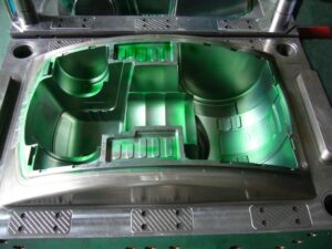
The two-plate mold is so named in light of the fact that it comprises of two amassed areas that sandwich the dissolve; every 50% of the form can comprise of at least one mold plates. A segment of an isometric mold is given in Fig. 6.4, in which the concealing speaks to the movement of the polymer liquefy. During the embellishment cycle, the spout of the trim machine mates with the span of the sprue bushing. The polymer dissolve first streams down the sprue bushing, accordingly crossing the thickness of the top brace plate and A plate. The material at that point streams over the splitting plane through sprinters and entryways into at least one mold pits.

After the polymer is completely infused and set, the mold is opened at the splitting plane, which is situated between the An and the B plates. Regularly, the A portion of the mold stays fixed while the B half of the form is pulled away with the moldings and sprinter framework staying on the center. To encourage launch, a converse mold is normally given on a take out pin beneath the sprue to guarantee that the sprue and appended sprinter stays with the B half. After the form has opened adequately to eliminate the moldings, the ejector plate is pushed forward by the embellishment machine. The sprue take out pin pushes on the sprue, breaking the little undercut and shooting the sprue from the B side of the mold. Extra ejector pins and take out pins can be put down the length of long sprinters to encourage launch of the feed framework.

In the plan of the feed system of oem/odm automotives injection molding factory, the length of the sprue is controlled by the joined thicknesses of the top clip plate and the A plate. The lengths of the sprinters are controlled by the situation of the depressions and the format of the related sprinters. Given this format, the mold creator needs to determine the widths of the feed framework. When all is said in done, the distances across of the upstream sprinters are bigger than the measurements of the downstream sprinters, since the progression of the polymer soften branches at sprinter intersections and there will be a lesser stream rate through every one of the downstream sprinters.

While a two-hole two-plate mold is utilized to show form plan ideas, the gave examination can be applied to more perplexing feed framework formats. For instance, china injection molded parts factory gives a feed system plan to an eight-cavity family form, including two essential sprinters, four optional sprinters, and eight tertiary sprinters. On the off chance that the stream rate through the sprue was 100 cc/s, at that point the stream rate through every one of the essential, optional, and tertiary sprinters would separately be 50 cc/s, 25 cc/s, and 12.5 cc/s. On the off chance that the stream obstruction in the depressions differed generously, nonetheless, at that point the stream rate in the tertiary sprinters could fluctuate considerably during the form filling stage.

Likewise with the feed system configuration appeared in oem/odm industrial mold factory, the distance across of each downstream sprinter is littler than the upstream sprinter appeared in Fig. 6.6. There is one prominent special case: the width of the trim machine’s spout opening is ordinarily littler than the distance across of the sprue delta. The littler opening in the machine spout gives a highlight division between the molded sprue and the cemented plug in the spout of the trim machine. In the event that the spout opening were bigger than the sprue bay, at that point a solidified part of plastic in the spout behind the sprue bushing could make the sprue adhere to the A portion of the mold. At the point when such staying occurs oftentimes, the decay may decide to perform a”sprue break” by withdrawing the infusion unit of the embellishment machine from the machine spout preceding mold opening and part launch. This activity is bothersome since it adds multifaceted nature and fluctuation to the embellishment cycle, so the form planner ought to check as well as suggest the spout hole measurement properly.

This article is from http://www.chinainjectionmold.com/

Mold Filling Control

During mold filling in high precision mould manufacturer, the polymer liquefy will in general stream radially all through the pit from where it is injected. When all is said in done, the mold ought to be planned with the end goal that the polymer dissolve arrives at the edges of the shape hole furthest from the entryway at around a similar time. Such in any event, filling considers more uniform and lower soften pressures all through the form hole.

On the off chance that one part of the mold by oem mold factory fills significantly sooner than different bits of the mold, at that point the dissolve in the filled bits will deteriorate with conceivably genuine outcomes. The filling molds from the examination of the bezel in which the plastic liquefy is infused at two areas. Each mold speaks to the area of the liquefy front at various minutes in time. As can be watched, the plastic dissolve streams radially out of the entryway and is then obliged by the side dividers. The polymer liquefy then streams at the edge dividers, at that point over the top and base dividers of the bezel.

During most of the filling of china mould produce services factory, the stream rates to the upper and lower parts / china custom mold components of the part are equivalent. Notwithstanding, the plastic was infused at entryways found somewhat toward the lower segment of the part, with the end goal that the base segment of the part fills before the upper segment of the part. At the point when the two liquefy fronts meet at the base place, almost no extra plastic soften can be constrained into the lower bit of the part. The stream to the base segment of the part deteriorates, causing a flood in the soften stream to the upper bit of the part. The subsequent imperfections can include:

■Excessive cavity filling constrains needed to fill the shape, inordinate clasp weight, and blazing;

■Inability to fill the shape depression (short shot);

■High leftover pressure and warpage; and

■Melt break, flying, delay, or other stylish deformities related with changes in dissolve speed during mold filling.

To evade or resolve these issues, the shape configuration ought to think about the sort and 10-cation of door, the format and measuring of the feed framework and the ostensible thickness of the shape cavities, and utilize slight changes in the divider thicknesses to deliberately coordinate the stream in the form hole.

In any event, when the mold fills consistently, cavity filling investigation might be utilized to boost the nature of the part. For example, it is here and there attractive to control the liquefy front headway with the end goal that weave _lines are put in zones of the part that are less significant regarding feel or basic uprightness. Essentially, cavity filling investigation might be performed to foresee the last territory to fill with the goal that vents as well as ejector pins are accommodated the uprooted gas to leave the shape. For anisotropic plastics, (for example, glass filled materials), cavity filling examination and configuration can be performed to control the stream bearing to influence the shaped in direction, quality, or shrinkage. This article is from http://www.chinainjectionmold.com.