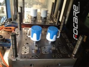
Klarm Mould Offers Large Size Mold China

The mold plan of liquid helped shape needs to change significantly from that of injection and co-injection molds. Specifically, the form planner needs to think about the area for the injection of the gas or water. As exhibited in mould manufacturers china both the spout and pit are normal areas. As significantly, the shape planner should cautiously plan the mold to have suitable stream channels to deliberately coordinate the gas or water through the shape cavity. In most shape plans, the cavity divider thickness is made as uniform as conceivable to stay away from nonuniform cooling and shrinkage. Notwithstanding, such a form configuration won’t prompt a successful shape for liquid help. The explanation is that the gas or water will pervade or”finger” in arbitrary bearings through a consistently thick mold pit, subsequently debilitating the trim without fundamentally diminishing the part weight. Thusly, thick stream diverts as demonstrated in Fig. 13.5 are regularly added to the shape hole to coordinate the gas or water through the form pit. Every one of the gas channels will show some anomaly paying little heed to the extent of infiltration. By and large, it is attractive to build up a gas channel to give as uniform a formed divider as could really be expected while giving the important liquid stream and part solidness. Thus, the upper right gas direct in Fig.13.5 is least liked. Since the other stream channels are cored out by the liquid, the cooling and shrinkage is made moderately uniform without broadened process duration.
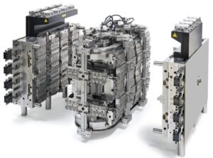
Water help shaping appears to have gotten expanded interest recently. Contrasted with gas help, water help gives at any rate three key advantages. In the first place, water has an exceptionally high explicit warmth thus can be injected to decrease the process duration contrasted and gas help shaping application. Truth be told, in some water help shaping applications, the stream channels are planned with deltas and outlets, to such an extent that the water can be coursed inside the molded part and accordingly enormously lessen heat move through heat convection. Second, water is in-compressible contrasted with gas, and S0 can be utilized by china mould design services to give higher soften pressures in the pit with less energy and hazard than gas. Third, it has been shown that water help gives more uniform and smooth surface in within the molded parts.

With these benefits, be that as it may, water help brings two huge impediments. To start with, the water should be eliminated from the inside of the molded parts; different plans from plastic injection mold manufacturers china have been created to eliminate the water inward to the trim before the form opening. Second, the utilization of water in the trim climate will in general expand dampness and consumption, so an erosion safe form material, for example, SS420 is suggested.

This is from http://www.chinainjectionmold.com
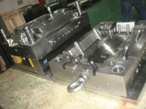
Klarm Mould Provides molds & tooling services china

Gas and water are the two liquids, so the two gas help embellishment and water help trim can be considered as kinds of liquid helped shaping cycles. Since these helping liquids are injected within a first material, all liquid help molding cycles can be viewed as a sort of co-injection molding interaction. Contrasted with conventional co-injection with polymer dissolves, liquid helped forming has two unmistakable contrasts for china precision injection plastic parts factory.

To start with, the second injected liquid (like nitrogen or water) has a low consistency contrasted with the recently injected polymer soften. This low thickness accommodates an exceptionally low pressing factor drop along the stream way, and consequently gives magnificent pressing factor transmission for pressing out the recently injected polymer dissolve. Second, the helping liquid is subsequently taken out from the formed part in order to burrow out within the shaped part. With cautious form plan, liquid helped moldings can have expanded strength, lighter weight, and diminished process duration contrasted with traditional or co-injected molds.

Liquid helped molding is a genuinely old cycle having filled in as a choice to injection molding for china precision plastic injection mold factory. Two varieties of a more current gas help measure with infusion decompression are appeared in Fig. 13.4 [7]. In the primary strategy, two shape parts 10 and 11 structure a form pit 12 into which the plastic dissolve will stream. The trim machine’s spout 13 has an inner center 16 with a sliding valve 19 that is impelled by packed gas on the other hand presented through gas lines 20 and 21 through three-way valves 22 and 23. Toward the start of the interaction, the plastic liquefy 24 is brought into the form pit through the machine spout 13; simultaneously, the sliding valve 19 is in a position which obstructs the gas bay cylinder 18 compacting the gas through line 21 decompressing the gas through line 20. After the form pit is somewhat filled, gas line 20 is compressed while gas line 21 is depressurized. This makes the sliding valve take on the situation as shown so that gas gulf tube 18 is opens and conveys compacted gas to the shape hole. When the gas has been injected, the sliding valve is then incited to forestall the undesired progression of the plastic dissolve. After the formed part cools, the launch of the shape makes the sprue break and the arrival of any packed gas to the surrounding climate.

A subsequent technique is additionally appeared in injection mold manufacturing china in which the opposite of injection pressure, injection decompression, is utilized to mold an empty part with a huge cavity. In this plan, the plastic liquefy streams into a cavity framed between two shape parts 30 and 32. While not appeared, these shape parts can have fine subtleties like supervisors that are full grown by the underlying filling of the depression with the polymer liquefy. The compacted gas is then infused into a thicker segment of the form cavity.

Simultaneously, the mold center 32 is withdrawn from its restricting mold half 30 to develop the cavity. Thusly, moldings with exceptionally huge interior holes (for instance, 50 mm) can be shaped while saving fine highlights on the outside surfaces of the formed part.

This article is from http://www.chinainjectionmold.com/

Klarm Mould Perfect Molding Design

For china industrial injection mold manufacturers, their end goal of structural design , a center can be viewed as shallow when the tallness of the center is not exactly both the width and length of the center. Shallow centers, for example, for the bezel form, won’t be exposed to exorbitant pressure or redirection brought about by the use of the soften strain to the side dividers of the center. Thusly, shallow centers can be planned by the recently depicted investigation for form plates. Profound centers need further thought of pressure and avoidance as next examined.

The vertical redirection of centers because of pressure by the soften can be displayed as recently examined in Section 12.2.1, however with the compressive powers and cross-sectional regions proper for the center as demonstrated as a visual cue.

The underlying model of profound centers is additionally confounded since profound centers can twist because of the utilization of parallel powers from the liquefy pressure against their sides. Center twisting might be a critical issue when centers are thin and have a low firmness related with their cross-sectional region, es pecially when the centers are dug out to accommodate shape coolant. Investigation and plan of the center should guarantee that the potential center redirection isn’t inordinate and that the compressive anxieties around the border of the center are adequate, These two concerns are next tended to.

In the injection moulding services, it might create the impression that the cooling embed in the plan of Fig. 12.25 will completely uphold the center addition. While this presumption may demonstrate satisfactory, a more vigorous plan is given by expecting that the cooling embed offers no help. There are two explanations behind making this supposition. To start with, the external surfaces of the cooling addition may not firmly fit the inward surfaces of the center supplement. Any leeway or hole more noteworthy than the diversion of the center will totally forestall the cooling embed from supporting the center. Second, the cooling addition might be produced using an unexpected material in comparison to the center supplement, like aluminum. At that point, the cooling supplement probably won’t withstand the burdens im presented while sup porting the center addition.

The absolute diversion of the top surface of the center can be assessed by superimposing the pressure of the side dividers with the twisting of the top surface. While the compressive pressure dissemination in the side dividers of the center isn’t completely uniform, the normal pressure is around the applied power from the top isolated by the cross-sectional region of the side dividers.

China injection mold maker knows it well that bending from the edge of the top surface to the focal point of the center can be determined utilizing pillar or plate bowing conditions of Section 12.2.2 and added to the relocation because of pressure to appraise the absolute vertical redirection.

This article is from http://www.chinainjectionmold.com/