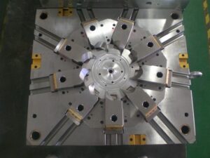
Klarm Mould Perfect Molding Design

For china industrial injection mold manufacturers, their end goal of structural design , a center can be viewed as shallow when the tallness of the center is not exactly both the width and length of the center. Shallow centers, for example, for the bezel form, won’t be exposed to exorbitant pressure or redirection brought about by the use of the soften strain to the side dividers of the center. Thusly, shallow centers can be planned by the recently depicted investigation for form plates. Profound centers need further thought of pressure and avoidance as next examined.

The vertical redirection of centers because of pressure by the soften can be displayed as recently examined in Section 12.2.1, however with the compressive powers and cross-sectional regions proper for the center as demonstrated as a visual cue.

The underlying model of profound centers is additionally confounded since profound centers can twist because of the utilization of parallel powers from the liquefy pressure against their sides. Center twisting might be a critical issue when centers are thin and have a low firmness related with their cross-sectional region, es pecially when the centers are dug out to accommodate shape coolant. Investigation and plan of the center should guarantee that the potential center redirection isn’t inordinate and that the compressive anxieties around the border of the center are adequate, These two concerns are next tended to.

In the injection moulding services, it might create the impression that the cooling embed in the plan of Fig. 12.25 will completely uphold the center addition. While this presumption may demonstrate satisfactory, a more vigorous plan is given by expecting that the cooling embed offers no help. There are two explanations behind making this supposition. To start with, the external surfaces of the cooling addition may not firmly fit the inward surfaces of the center supplement. Any leeway or hole more noteworthy than the diversion of the center will totally forestall the cooling embed from supporting the center. Second, the cooling addition might be produced using an unexpected material in comparison to the center supplement, like aluminum. At that point, the cooling supplement probably won’t withstand the burdens im presented while sup porting the center addition.
The absolute diversion of the top surface of the center can be assessed by superimposing the pressure of the side dividers with the twisting of the top surface. While the compressive pressure dissemination in the side dividers of the center isn’t completely uniform, the normal pressure is around the applied power from the top isolated by the cross-sectional region of the side dividers.

China injection mold maker knows it well that bending from the edge of the top surface to the focal point of the center can be determined utilizing pillar or plate bowing conditions of Section 12.2.2 and added to the relocation because of pressure to appraise the absolute vertical redirection.

This article is from http://www.chinainjectionmold.com/
Ejector Pin

The bigger freedom between the ejector pin and the ejector through-opening not just serves to wipe out the sliding rubbing between the pin and the plate, yet in addition gives required slop to permit to misa lignment between the tomahawks of the ejector openings in different plates. The predetermined freedom ought to surpass the absolute stack-up of the openings’ positional resiliences over the form plates. Since ordinary boring resiliences are on the request for 0.25 mm, a diametral leeway of 0.5 mm should be adequate in most shape making applications. Moreover, a liberal chamfer should be given at the interface between the center addition and the help plate. As shown in china high-precision mould suppliers, this chamfer helps the controlling of the ejector pin from the help plate into the center addition during mold get together.

The definite plan of the ejector retainer plate is appeared in injection moulding services china. As appeared in Detail D, a counterbore is given in the ejector retainer plate to pull the top of the ejector pin(s) away from the splitting plane of the shape when the ejector framework is being withdrawn. To give leeway to misalignment of the places of the ejector openings, the counterbore is given a liberal resilience so the centerline of every ejector pin is represented by the mating of the pin with the reamed ejector opening in the center supplements. In the event that a shaped pin is utilized, the top of the pin is normally given a level as appeared in Detail E. An equal space and finding dowel are given in the ejector retainer plate to keep up the right direction of the formed ejector pin.

At whatever point conceivable, the shape architect ought to indicate a similar length and width of ejector pins to encourage form gathering and upkeep. On the off chance that distinctive ejector pins are utilized in the form plan, the shape fashioner and shape creator should make certain to key and name every ejector pin and coordinating area on the ejector retainer plate so the shape can be promptly kept up by the disintegrate. The form fashioner ought to consistently try not to plan ejector sticks that fluctuate just somewhat in their plan, since comparable pins may incidentally be viewed as exchangeable by the disintegrate.


The erroneous gathering of ejector pins may make harm the pins just as the restricting mold hole surfaces.

Ejector pins are normally hot manufactured and rotundly ground from hard prepares, (for example, H 13). Stubsequently, the pins are nitrided and cleaned to give an exceptionally hard and smooth surface for low wear and rubbing. Ejector pins are accessible from a few providers in standard measurements (going from 1 mm to 25 mm) and lengths (from 150 1mm to 500 mm). Ordinarily, form creators cut and pound standard ejector pins to the completed length and shape indicated in the shape plan. Be that as it may, ejector pins might be exclusively requested with changing alternatives including distinctive mate rials or surface treatuments, exact diarneters or lengths, strings for mating with the ejector plate, pads, grooves, and so forth While ejector pins are accessible in a scope of breadths and lengths, particularly long pins with little distances across should be dodged, The explanation is that such thin pins will in general clasp under burden. As appeared in plastic injection moulded components china, the stacking of an ejector pin relates to a section with the top end upheld by the drag of the ejector opening, and the base end stuck by the ejector retainer plate. On the off chance that the compressive burden become too huge, at that point the pin may bow or lock an obscure way.

This article is from http://www.chinainjectionmold.com/

Vent Dimension

When the quantity of vents is indicated, the pace of wind stream through each vent can be determined by china high-precision mould suppliers. It might appear to be sensible to gauge the wind current through each vent as the absolute volumetric wind stream partitioned by the quantity of vents. Nonetheless, this methodology would not be moderate. The explanation is that the specific area of the finish of fill isn’t known. All things considered, it is conceivable that a great part of the wind stream can excessively support any of the four areas on each side of the part. A more traditionalist methodology is to expect that all the neighborhood wind current ways out through each accessible vent.

When all is said in done, the length and width of the vent are controlled by the application math. The base vent thickness is identified with the compel drop over the vent important to deliver the uprooted air. The base thickness can be determined utilizing examination of the air as a laminar, gooey stream as indicated by the Newtonian model recently introduced. While air moving through vents might be better displayed as a compressible, violent stream, the accompanying investigation is easier while additionally incredibly moderate. The weight drop of a Newtonian liquid in a rectangular channel.

It is again accentuated that the past investigation and model are moderate since the investigation expected laminar stream for the air thus proposes higher weight drops and the requirement for thicker vents than a tempestuous stream, the calculation and cycle conditions apply to a solitary, little vent with moderately high wind current, and the accepted thickness of air at room temperature is higher than would happen if the air were warmed by the polymer soften or pressure. Consequently, the base thickness of the vent won’t by and large be a restricting plan limitation.

The greatest size of the vent is identified with the most extreme measure of blazing that is average at the vent areas. The development of blazing in incredibly dainty channels, for example, vents is a serious examination point, requiring transient reproduction coupling the warmth move and liquid stream just as a profoundly refined work with extremely little league steps. No basic explanatory arrangement exists. Notwithstanding, with the end goal of conversation just, think about the use of laminar gooey stream. The normal volumetric stream pace of the liquefy during the blazing.

Since the above investigation might be hard to apply given the imperative presumptions, a few suggestions for vent thickness are recorded by china industrial injection mold manufacturers from different handbooks. The distinctions in the proposals are fascinating and reasonable to a limited extent. Most of the fluctuation probably originates from the way that there has been a drawn out pattern in the plastics business to move to more slender dividers, quicker injection rates, and higher injection pressures; the greatest thickness of the vent diminishes with expanding melt pressure. Simultaneously, material producers have tried to diminish the consistency of plastic tars while improving auxiliary properties. Appropriately, it ought not be astonishing that the specialized guidelines for vents change, with more slender vents being as of late suggested.

This article is from http://www.chinainjectionmold.com

Venting

Venting is regularly a minor part of mould plan for any china industrial injection mold manufacturers, and habitually dismissed until trim preliminaries demonstrate shape deficiencies identified with venting. A comprehension of the reason and capacity of vents can help the form planner to configuration vents where unmistakably required and guarantee that the shape may oblige extra vents when required.

The essential capacity of the vent is to deliver the air in the shape that is being dislodged by the profoundly pressurized plastic dissolve. In the event that all the air in the depression isn’t taken out during the filling stage, at that point a few imperfections can result. To begin with, the caught air can shape an exceptionally pressurized pocket in the form depression through which the soften can’t stream, framing a short shot in the formed item. Second, the profoundly compacted, high temperature gas can combust within the sight of the plastic liquefy, causing a marvel known as”dieseling”and an imperfection known as”burn marks.” If the consume marks show up on a tasteful surface, the disintegrate should dismiss the shaped part. Third, the presence of gas between two merging melt fronts can diminish the part quality because of impedance of the air with the two welding liquefies while likewise shaping v-indents on the outside of the formed part that go about as a pressure focus during the part’s end use.

Since an absence of venting is related with a few noteworthy imperfections, numerous wide and thick vents are attractive at various areas to encourage the wind stream out of the hole. In any case, on the off chance that a vent is excessively thick, at that point the polymer soften can leak out of the vent, causing a slim however sharp line of plastic blaze to shape at the vent areas. In many embellishment applications, this glimmer should be managed by the machine administrator utilizing a deburring instrument. Such deflashing is bothersome since the administrator causes work cost at this point doesn’t give 100% consistency. Moreover, on the off chance that a disintegrate proceeds with activity with unreasonable blazing, at that point the form’s splitting plane can wear and require reemerging. Thus, less and littler vents are liked.

The utilization of vents additionally by injection mould tooling china gives more highlights on the shape that can require support. Numerous polymers will off gas in the liquid state, delivering particles that can develop and obstruct the venting framework. Such stopped up vents can happen particularly rapidly with the utilization of form discharge. Subsequently, the trim cycle may discontinuously create deserts identified with an absence of venting. Many decays settle this issue by fusing vent cleaning as a component of a preventive support program. Regardless, the shape fashioner ought to endeavor to configuration venting frameworks that require insignificant support, and are anything but difficult to keep up when required.

A three stage investigation measure is suggested to injection moulding services for the examination and plan of vents. To begin with, the air relocation rate should be assessed comparative with the liquefy stream rate. Second, the number, type, and area of vents must be evaluated. Third, the width, length, and thickness of each vent must be determined. Regarding the thickness choice, the thickness must be more noteworthy than some base an incentive to guarantee sufficient venting while additionally littler than some most extreme add up to maintain a strategic distance from inordinate glimmering.

This article is from http://www.chinainjectionmold.com/
Mold Partial Design

For china high-precision mould suppliers, the expression “parting line” alludes to the area at which the pit embed, the center addition, and the plastic trim meet. Since the center and depression embed meet at this area, any huge avoidance of the cavity embed away from the center supplement will bring about a hole into which the plastic will stream and structure a dainty film of plastic known as “streak.” Imperfections in the center and cavity embeds at this area, for example because of wear or inappropriate dealing with, will likewise make holes into which the plastic will stream. Indeed, even with new and all around made molds, the area of the splitting line as a rule brings about a slight “witness line” along its length.

Therefore, the splitting line ought to be situated along a base edge of the part, or some other non-visual, nonfunctional edge. Think about the past cup. Setting the splitting line extremely near the lip as shown by the ran line in the left drawing would bring about an observer line and conceivable glimmer that may make the molded cup unusable. A superior area for the splitting line is at the base of the edge as demonstrated, relating to the splitting line.

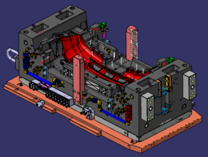
During injection moulding services china, for the PC bezel, the splitting line will be situated around the base edge of the part. It is seen that, in contrast to the cup, the splitting line for the bezel isn’t in a solitary plane. Or maybe, the splitting line follows the profile of the highlights as an afterthought dividers. This separating line is needed to fit the center addition, which hollows out the mold cavity to frame the openings required for the different connectors. As will be found in the following area, this mind boggling separating line mold will cause a more perplexing splitting plane.

When the splitting line is recognized, the splitting plane is extended outwards from the part to isolate the center supplement from the hole embed. The pit addition will mold the external and top surfaces of the part, while the center supplement will frame the edge and internal surfaces. For the PC bezel, the splitting line can be transmitted outward to frame the splitting surface. It tends to be seen that the entirety of the out-of-plane highlights along the splitting line n0w become complex surfaces on the splitting plane.

These surfaces present two huge issues during mold activity. To begin with, any misalignment between the sharp highlights on center and depression additions will cause wear between the sliding surfaces if not an inside and out effect between the main edge of the center and the mating pit surface. Second, the brace weight applied on the center and depression additions can make the surfaces lock along with outrageous power, causing exorbitant pressure and potential mold twisting during mold activity of china injection design service.

To evade inordinate pressure, interlocking highlights on the splitting plane ought to be slanted at any rate five degrees comparative with the mold opening course. The splitting surface is presently regularly made by means of three-dimensional PC supported plan (“3D CAD”) utilizing lobbed surfaces. Each hurled surface mixes a bended element along the splitting line to a line of comparing width on the splitting plane. The outcome is a surface with the required profile at the splitting line and the important draft down to the splitting plane. The hurled surfaces are then weave along with the splitting plane to give a splitting surface, as appeared for the bezel. These surfaces might be legitimately machined utilizing PC mathematically controlled (CNC) machining 0r by means of plunge electrical release machining (EDM) utilizing at least one anodes that were CNC machined.

This article is from http://www.chinainjectionmold.com/.