Ejector Pin

The bigger freedom between the ejector pin and the ejector through-opening not just serves to wipe out the sliding rubbing between the pin and the plate, yet in addition gives required slop to permit to misa lignment between the tomahawks of the ejector openings in different plates. The predetermined freedom ought to surpass the absolute stack-up of the openings’ positional resiliences over the form plates. Since ordinary boring resiliences are on the request for 0.25 mm, a diametral leeway of 0.5 mm should be adequate in most shape making applications. Moreover, a liberal chamfer should be given at the interface between the center addition and the help plate. As shown in china high-precision mould suppliers, this chamfer helps the controlling of the ejector pin from the help plate into the center addition during mold get together.

The definite plan of the ejector retainer plate is appeared in injection moulding services china. As appeared in Detail D, a counterbore is given in the ejector retainer plate to pull the top of the ejector pin(s) away from the splitting plane of the shape when the ejector framework is being withdrawn. To give leeway to misalignment of the places of the ejector openings, the counterbore is given a liberal resilience so the centerline of every ejector pin is represented by the mating of the pin with the reamed ejector opening in the center supplements. In the event that a shaped pin is utilized, the top of the pin is normally given a level as appeared in Detail E. An equal space and finding dowel are given in the ejector retainer plate to keep up the right direction of the formed ejector pin.

At whatever point conceivable, the shape architect ought to indicate a similar length and width of ejector pins to encourage form gathering and upkeep. On the off chance that distinctive ejector pins are utilized in the form plan, the shape fashioner and shape creator should make certain to key and name every ejector pin and coordinating area on the ejector retainer plate so the shape can be promptly kept up by the disintegrate. The form fashioner ought to consistently try not to plan ejector sticks that fluctuate just somewhat in their plan, since comparable pins may incidentally be viewed as exchangeable by the disintegrate.

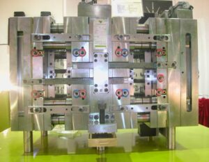
The erroneous gathering of ejector pins may make harm the pins just as the restricting mold hole surfaces.

Ejector pins are normally hot manufactured and rotundly ground from hard prepares, (for example, H 13). Stubsequently, the pins are nitrided and cleaned to give an exceptionally hard and smooth surface for low wear and rubbing. Ejector pins are accessible from a few providers in standard measurements (going from 1 mm to 25 mm) and lengths (from 150 1mm to 500 mm). Ordinarily, form creators cut and pound standard ejector pins to the completed length and shape indicated in the shape plan. Be that as it may, ejector pins might be exclusively requested with changing alternatives including distinctive mate rials or surface treatuments, exact diarneters or lengths, strings for mating with the ejector plate, pads, grooves, and so forth While ejector pins are accessible in a scope of breadths and lengths, particularly long pins with little distances across should be dodged, The explanation is that such thin pins will in general clasp under burden. As appeared in plastic injection moulded components china, the stacking of an ejector pin relates to a section with the top end upheld by the drag of the ejector opening, and the base end stuck by the ejector retainer plate. On the off chance that the compressive burden become too huge, at that point the pin may bow or lock an obscure way.

This article is from http://www.chinainjectionmold.com/
Pressure Drop and Gate Freeze

In the event that in oem/odm industrial injection moulding design factory the shear rates are inside as far as possible, at that point the weight drops are likely satisfactory too, However, the weight drop through the entryway ought to be determined to guarantee that sufficient infusion pressure is accessible to fill the shape pit; door measurements can likewise be acclimated to change the area of weld-lines in the form cavity. The weight drops are determined by the recently given conditions to gooey stream in strips and chambers. For reference, the formulae for Newtonian and force law streams are given.

In assessing the weight drop through doors, it is essential to figure the consistency at the fitting shear rate when utilizing the Newtonian model, or on the other hand utilize the conditions for the force law model. The weight drop through the doors may shift from right around zero to a few MPa. Weight drops over 10 MPa are normally characteristic of inappropriately planned entryways that are either excessively slight or excessively long.

After the shape depression is loaded up with the polymer soften, extra material must be constrained into the hole to make up for volumetric shrinkage as the dissolve cools. As the liquefy in the hole cools, the soften in the entryway will likewise will in general cool. The solidified skin will engender from the form divider to the centerline of the entryway. Since no extra soften stream can be provided to the cavity once the door freezes, the disintegrate should set up the embellishment machine to end the pressing stage at entryway freeze off and start the plastication stage. The door freeze time must be adequate to take into account pressing of the polymer in the form depression.

The cooling of the liquefy in the cavity and the utilization of the related warmth condition will be talked about in pom moulding parts manufacturers china. Utilizing the gave investigation, the mass liquefy temperature is plotted as a component of time for a 2 mm measurement barrel shaped entryway for ABS at midrange dissolve and coolant temperatures. The mass temperature of the polymer in the door will at first be near the set dissolve temperature of 240°C,and at that point decline in the post-filling stage as the warmth moves to the colder shape dividers. It would in the end arrive at the shape coolant temperature of 80°C.

Injection molding service china utilizing the Cross WLF consistency model, the evident thickness of the polymer dissolve in the door at a shear pace of 10 1/s is likewise plotted in Fig. 7.18. It is seen that the consistency of the plastic liquefy is at first low, and afterward starts to increment exponentially as the temperature diminishes. In the end, the consistency will increment with the end goal that no stream is successfully communicated through the entryway and the pressing stage should end, For this situation, a thickness of 100,000 Pa s has been subjectively chosen as a”no-stream” condition, relating to a door freeze season of about 1.5 s. Supplement A gives the “no-stream temperature”for different materials assessed as such.

For reference, the conditions to ascertain the door freeze time are accommodated rectilinear and strip calculations. These conditions will give the base pack times since they expect flawless warmth conduction between the soften and the shape divider. Practically speaking, entryway freeze times will be longer since these conditions don’t consider the soften course through the door into the hole and the related convection of warmth that will in general forestall the freezing of the entryway. Hence, the length of the pressing stage ought to be relied upon to be fairly longer than those anticipated with the conditions. All things being equal, the conditions are helpful to give a gauge of the significant degree of the polymer cementing time in the entryway.

This article is from http://www.chinainjectionmold.com.