Heat transfer Control

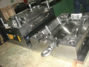
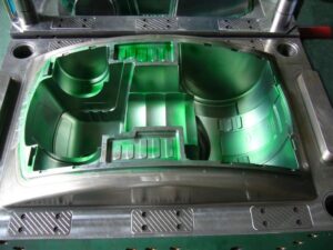
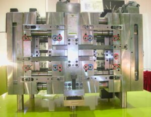
oem/odm industrial injection moulding design factory should take the heat transfer into consideration when making the inject molds. Given the troubles related with dynamic shape divider temperature control, a “latent” cooling configuration has been created by china high precision mold manufacturer; the expression “passive”is used to suggest that the form doesn’t use any outside capacity to control the form divider temperature. The plan appeared in injection mould factory was explicitly evolved to control the shape divider temperature during the embellishment of optical media. The shape incorporates two parts 12 to frame a form hole 14. Cooling lines 20 are given for each traditional plan to eliminate the warmth from the polymer soften. Notwithstanding, a warm protecting part 22 is put between the shape parts 12 and the stampers 31 and 33. The warm protecting part 22 is produced using a low thermally conductive material, ideally a high temperature polymer, for example, polyimides, polyamideimides, polyamides, polysulfone, polyethersulfone, polytetrafluoroethylene, and polyetherketone. The protecting polymer is normally turn covered in an uncured structure to give a layer a thickness on the request for 0.25 mm and accordingly heat relieved. The stamper 33 is commonly manufactured from nickel, and gives the surface subtleties to replication while additionally ensuring and giving the separator a uniform, exceptionally cleaned surface during embellishment.

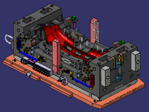
During embellishment, the protecting layer 22 behind the stamper 33 eases back the underlying cooling of the tar during the trim activity. Due to this protection, the stamper’s temperature increments and s0 the skin layer holds heat longer during the shape filling stage, accordingly staying away from the surface anomalies made by quick surface cooling. The temperature of the stamper:melt interface can be constrained by determination of the cycle conditions just as the layers’ thicknesses and material properties; one dimensional cooling examination can be utilized by plastic precision injection mould factory to comprehend the physical science and aid the plan streamlining. In this model, it was discovered that the centerline temperature 51 of the plate directs the base cooling time for the part to cool underneath the glass change temperature of the polymer dissolve. The temperature 52 at the stamper:melt interface impacts the warm pressure and pit replication on the circle’s surface and is estimated. The temperature 53 in the form behind the separator recommends that the shape goes about as a warmth sink and is kept up at a significantly steady temperature.

The shape fashioner and measure specialist ought to instinctively comprehend that the expansion of a protecting layer will in general diminish the pace of warmth move from the soften to the form, and in this way require expanded cooling times. To lighten this issue, the cooling lines can be worked at a lower temperature to accommodate higher paces of warmth move after the underlying warming of the stamper. Likewise, this plan methodology for the plastic injection moulded components china gives a sensible degree of shape divider temperature control with no extra energy utilization or control frameworks. Nonetheless, the degree of temperature control is restricted contrasted with the other air conditioning tive warming plans. Furthermore, this methodology might be dififcult to apply to complex three-dimensional calculations.

This article is from http://www.chinainjectionmold.com/.

Mold Wall

The investigations and plans introduced for mold cooling are sufficient for most inject molding applications in oem/odm automotives mould factory. In any case, there are a few applications wherein the utilization of customary cooling plans is unsatisfactory. Regularly, the improvement of a set skin happens when the hot polymer dissolve contacts the virus form divider. In some trim applications, the solifed skin may prompt untimely freeze off of the liquefy in the pit, unnecessary birefringence in the formed part, or insufficient degrees of sparkle or surface replication. In different applications in china precision injection plastic parts factory, mold divider temperature vacillations over the outside of the form hole may prompt an absence of dimensional control. In that capacity, some trim applications including focal points, plane cockpit overhangs, optical capacity media, and fiber fortified materials may try to improve the nature of the moldings through unique control of the mold divider temperature. A few distinct systems are next examined.

One way to deal with controlling the form divider temperature is to utilize at least one lots of cooling channels to effectively warmth and afterward effectively cool the mold. One such mold configuration is appeared in china high precision mold manufacturer; this was created to give tight resiliences when forming profoundly delicate plastic materials or exceptionally slim walled moldings. In this beat cooling plan, a mold hole 7 is framed by a hole embed 10 and a center supplement 9. The center addition is intentionally intended to be as thin as could be expected under the circumstances, and encompasses an inside center 12 to give a channel 14 to course for temperature controlled liquids. The cavity embed 10 is correspondingly intended to mate with the cavity plate 28 and the external supplement 29 to frame channels 24 and 25.

In activity, two liquids are independently temperature controlled with a warming gadget 35 and a cooling gadget 34; two separate liquids are prescribed to diminish the expense and time related with consecutively warming and cooling a solitary liquid.

Preceding the infusion of the polymer soften, the control valves 36 and 37 will guide the warmed liquid to the delta 18 and through the mold center by means of channels 14 and 15 preceding returning through the outlet 16; a comparative warming circuit is framed for the form hole through components 26, 22, 25, and 27. When the additions 9 and 10 are at a temperature over the point of solidification of the plastic soften, the plastic liquefy is injected into the depression 7. The control valves would then be able to be impelled to coordinate the cooling fl1uids from the cooling gadget 34 through similar channels recently utilized by china injection mold factory for warming.

The achievement of this mold configuration is profoundly reliant on limiting the mass of the form steel and coolant needed to frame and cool the dividers of the mold hole. It is plainly attractive to limit the thickness of the form embeds, the length of the cooling channels and lines, and the warmth move to nearby mold parts. In this plan, air holes 20, 29, and 38 are utilized to lessen the measure of warmth move thus improve the warm effectiveness and dynamic execution of the mold; protecting sheets (not numbered) are additionally given neighboring the top and back cinch plate to limit heat move to the platens. Shockingly, the size of the pit and the basic prerequisites on the form parts requires the utilization of genuinely huge mold segments that should be warmed and therefore cooled. The dynamic warm reaction is restricted.

This article is from http://www.chinainjectionmold.com

UC Cycle

The UC cycle approach, with its exceptional capacity to develop parts in a”cold” strong state design, holds extraordinary guarantee, particularly if the base metal ability can be extended to satisfy new market needs. The framework inalienably fits delivering metal parts with fantastic dimensional control and material properties because of a few interesting cycle attributes:

  • Solid-state creation There is no fluid to metal change in the UC cycle, along these lines dimensional exactness effectively meets designing necessities that are out of sight go after numerous other direct metal cycles. This permits fast creation and ongoing component age. Also, the chilly statement measure fits the consolidation of help materials that must be utilized in temperature goes well underneath the liquefying purpose of the material with the goal that hardening happens, in this manner utilizing the additional solidness and unbending nature for complex part fabricating.
  • Integrated three-pivot processing focus UC is a mixture added substance metal cycle in that the testimony stages are intermittently trailed by exact material evacuation stages utilizing customary CNC innovation. This is made conceivable in huge part to the point noted previously.
  • Ultrasonic bond quality-The UC cycle uses ultrasonic joining of dainty foil layers for a strong state measure. The resultant interlaminar bond quality is that of a metal lurgical bond and is portrayed by fine grain structures not at all like the coarse recast layers normal inside different cycles.
  • Multimaterial covers UC empowers holding and joining of different materials, for example, glass metals, Al-Ti, Cu-Al and so forth Table 6.3 shows the huge number of thermodynamically viable materials blends under UC conditions. These materials can possibly be utilized in this UC cycle.

The ultrasonic welding parts of the Formation machine are depicted in this segment. As appeared in Figure 6.76, the sonotrode is a finished chamber that cinches the added substance layer or foil (or tape) to the substrate and vibrates at ultrasonic frequencies and micron-scale amplitudes. In the ideal case, the sonotrode and new layer move together and the vibration energy is moved from the sonotrode-tape interface (STI zone) into the tape-substrate interface.

This tape- – substrate interface disfigured district, called distortion influenced zone. (DAZ), encounters plastic disfigurement that breaks and scatters surface oxides and foreign substances, accordingly bringing molecularly clean metal surfaces into contact and making a genuine metallurgical bond. Figure 6.77 shows the microstructure of the DAZ disfigured district.

Solidica utilized RPCAM programming to consolidate the standard 3D CAD model into the affidavit and processing methodology inside the CNC machine code for part fabricating. A case of an injection shape created as such is appeared in china plastic rapid prototyping suppliers.

These consolidated credits of the framework empower such plans as a completely incorporated conformal cooling framework without the utilization of jolts and sealants, and different parts. This altogether decreases costs in materials, work, and time to showcase. Another model is appeared in precision cnc prototype manufacturers.

The UC cycle can be further illustrated in sheet metal rapid prototyping manufacturers china shows two pieces of materials to be welded. Figure 6.80b shows the materials are welded utilizing a moving sonotrode. Figure 6.80c shows the machining activity after the materials are welded. Figure 6.80d shows the roundabout shape subsequent to machining. Figure 6 .80e shows the welded part with the third strip machined to a space in the middle. Figure 6.80f shows the part with the fourth strip. Along these lines, UC can be utilized to create some interior pits. By utilizing ultrasonic welding and machining, complex calculations and ideal plans would now be able to be acknowledged where ordinary machine apparatus cycles would not have the option to deliver such highlights.

In synopsis, the upsides of the UC cycle incorporate the accompanying:

  • Directly manufacture metal items from modest foil feedstock
  • Incorporate complex interior calculations, depressions, and channels
  • Functionally reviewed composite assembling capacities
  • High highlight to-include exactness (+0.002 to around +0.005 in.)
  • High fa brication speed
  • Low measure heat
  • Low cost contrasted with utilizing high fuel source to create metals
  • Reduced optional machining activities
  • Stop and restart to work whenever

The uses of the UC cycle incorporate venture projecting, vacuum shaping, blow forming, infusion forming, and direct aluminum model parts. Notwithstanding framing metallurgical securities, plastic stream created by ultrasonic excitation is sufficiently able to typify an assortment of strengthening materials. Fiber composites can be collected by setting the filaments between layers of metal foils. High quality strands, for example, silicon carbide and boron can be installed to make firm boards, while 2D lattices can advance isotropy. Shape memory composites like nitinol can be incorporated with an aluminum lattice to make smart portable parts. Sensors, for example, thermocouples or strain gages can likewise be embedded. This cycle is a decent mechanized choice to paste, screws, or snap-fit plans, yet it is generally utilized in applications for little pieces, for example, watches, tapes, toys, and clinical devices by the micro machining machined parts manufacturers china. The uses of ultrasonic metal welding are quickly growing, and it has just been demonstrated relevant to the car aluminum case, for example, the all aluminum Jaguar.

This article is from http://www.chinainjectionmold.com/

Cutting Process

A shape cutting cycle uses the layered assembling procedure for quick prototyping in chinese laser cutting prototype manufacturers.

In any case, it varies from other RP frameworks in that, instead of working up a section by adding materials to a stack through a shaping cycle, layers of sheet materials, for example, paper, plastics, or composites are appended to a stack, and a laser removes the unused parts.

A delegate shape cutting cycle is Laminated Object Manufacturing (LOM) created by Helisys Inc. in 1985. The cycle starts with a PC cutting a 3D strong model of the part into 2D cross-segments. Info information is in the STL document design. The thickness of the PC produced cross-segment compares to the thickness of the sheet material. The sheets can be 0.001-0.005 in. thick and a winding and a loosening up roll give a strip of the material. Figure 6.73 shows the schematics of a form cutting cycle. It is fit for creating parts that can be machined or sanded to give great surface completion, however since the parts are produced using paper, they should be fixed from dampness.

Profiles of item cross-segments are cut from paper utilizing a laser as appeared in precision cnc machining solutions factory. The paper is loosened up from a feed roll (A) onto the stack and clung to the past layer utilizing a warmed roller (B). The roller liquefies a plastic covering on the base side of the paper to make the connection between layers. The profiles are followed by an optics framework that is mounted to a X-Y stage (C). The cycle produces extensive smoke. Either a fireplace or a charcoal filtration framework (E) is required and the manufacture chamber (F) must be fixed.

After the cutting of the mathematical highlights of a layer is finished, the overabundance paper is removed to isolate the layer from the web. The additional paper of the web is twisted on a take-up move (D). The strategy is self-supporting for shades and undermines. Territories of cross-segments that are to be taken out in the last article are vigorously crosshatched with the laser to encourage evacuation. It very well may be tedious to eliminate additional material for some math.

In a shape cutting cycle, the material is situated onto the structure stage and a warmed roller moves over the outside of the material, holding it to the stack as appeared in Figure 6.74a. A X-Y situating table with mirrors and optics reflects and centers the CO2 laser bar, which cuts a profile of the part as appeared in plastic or metal machining parts china. The region of material encompassing the part profile is sliced in a crosshatch example to encourage its expulsion later by china precision machining services manufacturers. The abundance material left on the structure block goes about as a help structure for the following layer. Changes in the laser force and slicing speed empower it to slice through just each layer in turn. The stage brings down to oblige another layer of sheet material as appeared in fashion sheet metal rapid prototyping, in which the moves advance, and the warm roller bonds to the stack as appeared in Figure 6.74f. Another layer of material is then clung to the head of the recently cut layer. The laser cuts another cross-area as in Figure 6.74g and this cycle proceeds until the part is finished as appeared in Figure 6.74h.

This article is from http://www.chinainjectionmold.com/

Molding Principles

oem/odm medical mold design factory suggests that interminably high warmth move rates can be accomplished by moving to higher conductivity materials and utilizing many cooling lines extremely near the surface. In any case, there is a point where further interest in the cooling system receives no benefits. The explanation from the high precision molds made in china is that the warmth move rate becomes restricted not by the warmth conduction through the shape, yet rather by the warmth conduction through the plastic just as the warmth convection to the form coolant. Thus, molds made out of exceptionally conductive materials may have a huge decrease in the process duration by improving warmth conduction through the form, however nothing close to the eight-overlap improvement that may be foreseen from these material’s high warm conductivity esteems.

The way to planning a financially savvy form is to realize where to contribute. Profoundly conductive materials are amazingly powerful in certain applications and are typically simpler to machine, yet are not generally best. Thus, cooling line formats can go from the easy to the complex. Complex cooling line plans regularly require generous macintosh hining, stopping, fixing, fitting, and upkeep. It is significant for the form creator to know when the additional expense of an unpredictable cooling framework configuration is defended.

The liquefy will apply huge weights on the surfaces of the shape cavities. These powers make an interpretation of straightforwardly into noteworthy worries inside the form plates and embeds. The form’s auxiliary respectability is debilitated by each cooling line, every one of which requires the expulsion of supporting mold material and furthermore gives a pressure fixation.

While the effect of the cooling lines on the structure of the shape can be particularly intense in embellishment applications with high dissolve pressures, the potential effect stays noteworthy in many applications since the cyclic stacking and emptying of the soften pressure offers ascend to disappointment because of exhaustion. More terrible, erosion of the metal by the coursing coolant will in general fuel the pressure focuses. Breaks can frame, consume, and spread through the form to the pit and along these lines require fix.

Trim machine administrators from high precision plastic injection mould suppliers ought to have the option to work the injection mold with negligible data. The quantity of outside associations ought to be kept to a base, with ideally two associations (one bay and one outlet) per shape half. Every one of the associations ought to be labeled”in”and”out”to help the administrator abstain from framing a dead cooling circuit. Many disintegrates shading code gracefully lines (blue) and return lines (red), so shape arrangement is encouraged by correspondingly anodizing or giving hued names to the form gulfs and outlets. To evade harm to the cooling system, all outside segments ought to be recessed to maintain a strategic distance from direct contact with tie bars, work tables, or different iterms.

Given that there are numerous goals in the plan of the cooling system, it is improbable that each target will be all the while enhanced. The objective is for the mold architect to arrive at a decent trade off, with the end goal that quick and uniform cooling is accomplished in a savvy way. The accompanying seven stage investigation is given to help the mold plan choices that must be made. A while later, some basic cooling issues and plans are created.

This article is from http://www.chinainjectionmold.com/

Plane Vents

The principal kind of vent to be considered is the vent on the splitting plane. These vents are regularly given as exceptionally slight channels legitimately toward the finish of stream. Numerous molds are created with vents on the splitting plane that radiate from the edge of the splitting line outwards to a thicker vent”relief” or vent”channel.” Figure 8.6 gives a venting framework plan to the bezel, in which two vents have been given within and outside surfaces of the pit embed. The width of the vent, W, has been made deliberately high to accommodate vulnerability in the last territory of the liquefy to fill the pit. The thickness of the vent, hvent, has been determined as 0.05 mm, The length of the vent, L, is 2 mm, after which the wind currents through a 2 mm thick channel to a 3 mm distance across outlet situated at the middle and head of the addition.

While vents ought to be given on the splitting plane toward the finish of fill, it isn’t unprecedented for vents to be set intermittently around the outskirts of the cavity. For the trim of focus gated barrel shaped parts, vents can be set around the fringe of the whole form depression in high-precision mould china. In this plan, the pit for a top is focus gated as in a three-plate or hot sprinter form. A vent is put around the whole fringe of the shape depression. Given the adequate vent width, the vent is determined with a thickness of 0.015 mm and a length of 1 mm. A vent channel interfaces the vent ring to the side of the supplement and ensuing outlets.

While the above plans are absolutely viable regarding venting the uprooted air, it ought to be referenced that they are vulnerable to glimmering with twisting of the shape plates. As will later be examined in the auxiliary plan of Chapter 12, the dissolve pressure applies huge powers on the form pit and center. Any huge diversion will in general expand the thickness of the vents and in this way improve the probability and measure of glimmering. In reality, the plan of Fig. 8.7 might be particularly dangerous since the outside, base surface of the top is a region watched and dealt with by the end client. The utilization of an inward vent around the outskirts of a stripper plate will settle this issue as later planned in china mould manufacturing manufacturers.

To maintain a strategic distance from unreasonable glimmering and related support, it is suggested that vents on the splitting plane be utilized sparingly with a thickness on the request for 0.02 mm. On the off chance that venting is hence discovered to be lacking, at that point extra vents can be included or the thickness of existing vents expanded.

An exceptionally normal practice is to utilize the leeway around ejector pins for venting purposes. There are numerous preferences to this vent plan. To begin with, the incitation of the ejector serves to at any rate mostly clear the venting channel between the pin and the center. Second, ejector pins are normally utilized and surely known. Since a leeway should be indicated around the pin to give a sliding fit in any case, it is practical to determine a freedom appropriate for venting.

This article is from http://www.chinainjectionmold.com/

Vent Dimension

When the quantity of vents is indicated, the pace of wind stream through each vent can be determined by china high-precision mould suppliers. It might appear to be sensible to gauge the wind current through each vent as the absolute volumetric wind stream partitioned by the quantity of vents. Nonetheless, this methodology would not be moderate. The explanation is that the specific area of the finish of fill isn’t known. All things considered, it is conceivable that a great part of the wind stream can excessively support any of the four areas on each side of the part. A more traditionalist methodology is to expect that all the neighborhood wind current ways out through each accessible vent.

When all is said in done, the length and width of the vent are controlled by the application math. The base vent thickness is identified with the compel drop over the vent important to deliver the uprooted air. The base thickness can be determined utilizing examination of the air as a laminar, gooey stream as indicated by the Newtonian model recently introduced. While air moving through vents might be better displayed as a compressible, violent stream, the accompanying investigation is easier while additionally incredibly moderate. The weight drop of a Newtonian liquid in a rectangular channel.

It is again accentuated that the past investigation and model are moderate since the investigation expected laminar stream for the air thus proposes higher weight drops and the requirement for thicker vents than a tempestuous stream, the calculation and cycle conditions apply to a solitary, little vent with moderately high wind current, and the accepted thickness of air at room temperature is higher than would happen if the air were warmed by the polymer soften or pressure. Consequently, the base thickness of the vent won’t by and large be a restricting plan limitation.

The greatest size of the vent is identified with the most extreme measure of blazing that is average at the vent areas. The development of blazing in incredibly dainty channels, for example, vents is a serious examination point, requiring transient reproduction coupling the warmth move and liquid stream just as a profoundly refined work with extremely little league steps. No basic explanatory arrangement exists. Notwithstanding, with the end goal of conversation just, think about the use of laminar gooey stream. The normal volumetric stream pace of the liquefy during the blazing.

Since the above investigation might be hard to apply given the imperative presumptions, a few suggestions for vent thickness are recorded by china industrial injection mold manufacturers from different handbooks. The distinctions in the proposals are fascinating and reasonable to a limited extent. Most of the fluctuation probably originates from the way that there has been a drawn out pattern in the plastics business to move to more slender dividers, quicker injection rates, and higher injection pressures; the greatest thickness of the vent diminishes with expanding melt pressure. Simultaneously, material producers have tried to diminish the consistency of plastic tars while improving auxiliary properties. Appropriately, it ought not be astonishing that the specialized guidelines for vents change, with more slender vents being as of late suggested.

This article is from http://www.chinainjectionmold.com

Venting

Venting is regularly a minor part of mould plan for any china industrial injection mold manufacturers, and habitually dismissed until trim preliminaries demonstrate shape deficiencies identified with venting. A comprehension of the reason and capacity of vents can help the form planner to configuration vents where unmistakably required and guarantee that the shape may oblige extra vents when required.

The essential capacity of the vent is to deliver the air in the shape that is being dislodged by the profoundly pressurized plastic dissolve. In the event that all the air in the depression isn’t taken out during the filling stage, at that point a few imperfections can result. To begin with, the caught air can shape an exceptionally pressurized pocket in the form depression through which the soften can’t stream, framing a short shot in the formed item. Second, the profoundly compacted, high temperature gas can combust within the sight of the plastic liquefy, causing a marvel known as”dieseling”and an imperfection known as”burn marks.” If the consume marks show up on a tasteful surface, the disintegrate should dismiss the shaped part. Third, the presence of gas between two merging melt fronts can diminish the part quality because of impedance of the air with the two welding liquefies while likewise shaping v-indents on the outside of the formed part that go about as a pressure focus during the part’s end use.

Since an absence of venting is related with a few noteworthy imperfections, numerous wide and thick vents are attractive at various areas to encourage the wind stream out of the hole. In any case, on the off chance that a vent is excessively thick, at that point the polymer soften can leak out of the vent, causing a slim however sharp line of plastic blaze to shape at the vent areas. In many embellishment applications, this glimmer should be managed by the machine administrator utilizing a deburring instrument. Such deflashing is bothersome since the administrator causes work cost at this point doesn’t give 100% consistency. Moreover, on the off chance that a disintegrate proceeds with activity with unreasonable blazing, at that point the form’s splitting plane can wear and require reemerging. Thus, less and littler vents are liked.

The utilization of vents additionally by injection mould tooling china gives more highlights on the shape that can require support. Numerous polymers will off gas in the liquid state, delivering particles that can develop and obstruct the venting framework. Such stopped up vents can happen particularly rapidly with the utilization of form discharge. Subsequently, the trim cycle may discontinuously create deserts identified with an absence of venting. Many decays settle this issue by fusing vent cleaning as a component of a preventive support program. Regardless, the shape fashioner ought to endeavor to configuration venting frameworks that require insignificant support, and are anything but difficult to keep up when required.

A three stage investigation measure is suggested to injection moulding services for the examination and plan of vents. To begin with, the air relocation rate should be assessed comparative with the liquefy stream rate. Second, the number, type, and area of vents must be evaluated. Third, the width, length, and thickness of each vent must be determined. Regarding the thickness choice, the thickness must be more noteworthy than some base an incentive to guarantee sufficient venting while additionally littler than some most extreme add up to maintain a strategic distance from inordinate glimmering.

This article is from http://www.chinainjectionmold.com/

Pressure Drop and Gate Freeze

In the event that in oem/odm industrial injection moulding design factory the shear rates are inside as far as possible, at that point the weight drops are likely satisfactory too, However, the weight drop through the entryway ought to be determined to guarantee that sufficient infusion pressure is accessible to fill the shape pit; door measurements can likewise be acclimated to change the area of weld-lines in the form cavity. The weight drops are determined by the recently given conditions to gooey stream in strips and chambers. For reference, the formulae for Newtonian and force law streams are given.

In assessing the weight drop through doors, it is essential to figure the consistency at the fitting shear rate when utilizing the Newtonian model, or on the other hand utilize the conditions for the force law model. The weight drop through the doors may shift from right around zero to a few MPa. Weight drops over 10 MPa are normally characteristic of inappropriately planned entryways that are either excessively slight or excessively long.

After the shape depression is loaded up with the polymer soften, extra material must be constrained into the hole to make up for volumetric shrinkage as the dissolve cools. As the liquefy in the hole cools, the soften in the entryway will likewise will in general cool. The solidified skin will engender from the form divider to the centerline of the entryway. Since no extra soften stream can be provided to the cavity once the door freezes, the disintegrate should set up the embellishment machine to end the pressing stage at entryway freeze off and start the plastication stage. The door freeze time must be adequate to take into account pressing of the polymer in the form depression.

The cooling of the liquefy in the cavity and the utilization of the related warmth condition will be talked about in pom moulding parts manufacturers china. Utilizing the gave investigation, the mass liquefy temperature is plotted as a component of time for a 2 mm measurement barrel shaped entryway for ABS at midrange dissolve and coolant temperatures. The mass temperature of the polymer in the door will at first be near the set dissolve temperature of 240°C,and at that point decline in the post-filling stage as the warmth moves to the colder shape dividers. It would in the end arrive at the shape coolant temperature of 80°C.

Injection molding service china utilizing the Cross WLF consistency model, the evident thickness of the polymer dissolve in the door at a shear pace of 10 1/s is likewise plotted in Fig. 7.18. It is seen that the consistency of the plastic liquefy is at first low, and afterward starts to increment exponentially as the temperature diminishes. In the end, the consistency will increment with the end goal that no stream is successfully communicated through the entryway and the pressing stage should end, For this situation, a thickness of 100,000 Pa s has been subjectively chosen as a”no-stream” condition, relating to a door freeze season of about 1.5 s. Supplement A gives the “no-stream temperature”for different materials assessed as such.

For reference, the conditions to ascertain the door freeze time are accommodated rectilinear and strip calculations. These conditions will give the base pack times since they expect flawless warmth conduction between the soften and the shape divider. Practically speaking, entryway freeze times will be longer since these conditions don’t consider the soften course through the door into the hole and the related convection of warmth that will in general forestall the freezing of the entryway. Hence, the length of the pressing stage ought to be relied upon to be fairly longer than those anticipated with the conditions. All things being equal, the conditions are helpful to give a gauge of the significant degree of the polymer cementing time in the entryway.

This article is from http://www.chinainjectionmold.com.