Shrinkage

The point labeled”shrinking” relates to the second when the shaped polymer arrives at climatic weight. As of now, the polymer may start to contract, pull away from the form dividers, and create elastic burdens. The subsequent point, labeled”ejected,” compares to the second when the shape opens and the part is going to be catapulted. Upon launch, any created tractable anxieties may make the formed part unexpectedly shrivel. The formed part will at that point go through additional unconstrained shrinkage until equilibration and end-use, set apart as the point labeled”end use.” These volumetric shrinkage esteems can be utilized to assess the shaped part shrinkage. For the embellishment cycle plotted in plastic injection factory, the particular volume toward the beginning of shrinkage, discharge, and end-use are 1.116, 1.101, and 1.074 cc/g, separately. From these particular volumes, the anticipated in-form, post-trim, and all out shrinkage are, individually, 0.479%, 0.812%, and 1.291%.

Shrinkage in the thickness course was estimated in injection mold services china with a micrometer including a grasp wheel; a check dependability and repeatability study (check R and R, [10]) was performed with the standard deviation of the estimation being 2.9 um. The right-most section of china high-precision mould suppliers gives the assessed and noticed shrinkage results for each run of the DOE. Expansions in barrel and form coolant temperature brought about higher paces of anticipated shrinkage as (the mean shrinkage is 1.05 % for runs 1 to9 and 1.19% for runs 10to 18 at higher temperature). Expansions in pack pressure brought about lower anticipated shrinkage rates (the mean shrinkage is 1.21% for runs 1-3 and 10-12 at low pack pressure while of 0.95% for runs 7-9 and 16-18 at high pack pressure). The anticipated and noticed shrinkage had a Co-proficient of assurance, R, equivalent to 0.922. While there is some dissipate, the anticipated shrinkage is a sensible assessor for the noticed shrinkage.
Table 10.1 additionally breaks out the anticipated in shape and post form shrinkage dependent on the examination with the noticed weights and temperatures. It is intriguing that the size of the in – form and post – shape shrinkage are each huge supporters of the complete shrinkage, and that a significant part of the noticed conduct follows desires. For instance, the best anticipated post shape shrinkage compares to runs 10 to 12 that gave the least pack pressure and most elevated temperatures, which relates to the most volumetric shrinkage over the DOE runs. Reaction surface investigation was directed to fit a quadratic capacity to the information, with the dissolve pressure being the main determinant of shrinkage.

Contrasted with shrinkage assessment dependent on material provider direction, the trial examination measures the conduct of the shrinkage as a component of dissolve temperature and weight. The shrinkage examination would thus be able to be utilized by injection mould manufacturers in china for form plan in situations where the material properties and cycle conditions are known. The essential wellspring of change is anisotropic shrinkage identified with mathematical requirements inside the form during cooling. In particular, the ductile (canine bone) state of the shaped part will in general oblige the shrinkage in the length heading and hence drive more prominent shrinkage in the thickness course [11]. These outcomes and their constraints give trustworthiness and inspiration to more modern mathematical recreations that basically perform comparative examination on a more refined scale as recently talked about.

This article is from http://www.chinainjectionmold.com
Plane Vents

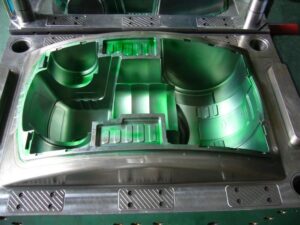
The principal kind of vent to be considered is the vent on the splitting plane. These vents are regularly given as exceptionally slight channels legitimately toward the finish of stream. Numerous molds are created with vents on the splitting plane that radiate from the edge of the splitting line outwards to a thicker vent”relief” or vent”channel.” Figure 8.6 gives a venting framework plan to the bezel, in which two vents have been given within and outside surfaces of the pit embed. The width of the vent, W, has been made deliberately high to accommodate vulnerability in the last territory of the liquefy to fill the pit. The thickness of the vent, hvent, has been determined as 0.05 mm, The length of the vent, L, is 2 mm, after which the wind currents through a 2 mm thick channel to a 3 mm distance across outlet situated at the middle and head of the addition.

While vents ought to be given on the splitting plane toward the finish of fill, it isn’t unprecedented for vents to be set intermittently around the outskirts of the cavity. For the trim of focus gated barrel shaped parts, vents can be set around the fringe of the whole form depression in high-precision mould china. In this plan, the pit for a top is focus gated as in a three-plate or hot sprinter form. A vent is put around the whole fringe of the shape depression. Given the adequate vent width, the vent is determined with a thickness of 0.015 mm and a length of 1 mm. A vent channel interfaces the vent ring to the side of the supplement and ensuing outlets.

While the above plans are absolutely viable regarding venting the uprooted air, it ought to be referenced that they are vulnerable to glimmering with twisting of the shape plates. As will later be examined in the auxiliary plan of Chapter 12, the dissolve pressure applies huge powers on the form pit and center. Any huge diversion will in general expand the thickness of the vents and in this way improve the probability and measure of glimmering. In reality, the plan of Fig. 8.7 might be particularly dangerous since the outside, base surface of the top is a region watched and dealt with by the end client. The utilization of an inward vent around the outskirts of a stripper plate will settle this issue as later planned in china mould manufacturing manufacturers.

To maintain a strategic distance from unreasonable glimmering and related support, it is suggested that vents on the splitting plane be utilized sparingly with a thickness on the request for 0.02 mm. On the off chance that venting is hence discovered to be lacking, at that point extra vents can be included or the thickness of existing vents expanded.

An exceptionally normal practice is to utilize the leeway around ejector pins for venting purposes. There are numerous preferences to this vent plan. To begin with, the incitation of the ejector serves to at any rate mostly clear the venting channel between the pin and the center. Second, ejector pins are normally utilized and surely known. Since a leeway should be indicated around the pin to give a sliding fit in any case, it is practical to determine a freedom appropriate for venting.

This article is from http://www.chinainjectionmold.com/

Molded Parts Cost Analyze

To China injection mold, here introduce a review of the form citing measure, including an itemized mold cost and part cost assessment technique. The system was created to use insignificant data but give the causal examination relating basic shape structure choices to the form cost and part cost. It is suggested that numerous quotes be produced for various form structures until an efective shape particular is built up.

In principle, the creation amounts ought to be known heretofore and used to plan an”optimal” shape for the predetermined amount. In actuality, the creation timetables and amounts are not accurately known, so the disintegrate and client should cautiously consider the conceivable consequence of utilizing molds that are finished or under-planned. Hence, elective form structures ought to be thought of and examined regarding breakpoints underway amount where diverse shape configuration approaches are liked.

Minimization of the absolute molded part cost is certifiably not a basic errand since injection mold and embellishment measures are ideally intended for various objective creation amounts. Regularly, there is a tradeoff between the forthright interest in the mold and later potential investment funds identified with the handling and material expenses per plastic injection moulded components china. Consider elective form plan and embellishment techniques for creating the bezel part with (1) a one: depression cold sprinter shape or (2) a two-hole hot sprinter form. The portrayed strategies have been applied to gauge the shape, material, and handling cost for these elective form structures with the outcomes summed up.

It is helpful to think about the all out expenses, Cotal, caused to create a given amount that is registered as where Crixed is the absolute expense of the form and its upkeep, ntotal is the complete creation amount over the life of the shape, and Cm’marginal is the all out negligible expense of the tar, machine, work, and vitality on a perpart premise. For a given form structure, the minor expense per piece will remain genuinely consistent over the life of the application (however there might be cost diminishes identified with disposal of deformities, decreases in process durations, and so on just as cost increments because of material estimating or delivery costs). To give the most ideal form structure and statement, numerous shape plans ought to be created for various objective creation amounts, and the complete creation costs assessed and looked at through breakeven investigation.

The cost investigation by injection moulding china company will regularly show the requirement for various form structures at very low and incredibly high creation amounts. In the past model, the forthright expense of the two-depression hot sprinter framework can’t be supported at low or moderate creation amounts. At higher creation amounts, be that as it may, a hot sprinter framework is fundamental to boosting benefit since the peripheral expenses of working the hot sprinter form are essentially not exactly those of the Cold sprinter shape. While the breakeven examination underpins clear structure choices at low and extremely high creation amounts, the shape configuration can be less sure at middle of the road creation volumes. In the event that the creation amount is on the request for 100,000 or 200,000 sections, at that point either shape configuration might be satisfactory from a 00St viewpoint. The client can be given the two structures to choose the elective that best accommodates their specialized necessities and business system.

Many decays and clients require a speedy rate of profitability thus will look at the all out c0st bend to acknowledge the utilization of a hot sprinter framework with higher cavitation just if an alluringly short restitution period can be accomplished. Some of the time, nonetheless, form plan choices are not founded exclusively on financial matters but instead by different concerns, for example,

(1)    The requirement for a form to allow quick shading changes, for which a hot sprinter feed framework may not be attractive.

(2)    The ability and inclination of the decay that will utilize the shape. In the event that the decay doesn’t have the experience or helpers needed to use a hot sprinter framework, at that point a cool sprinter shape may best be used.

(3)    The lean assembling procedures of the decays to diminish costs and improve quality. For example, it isn’t extraordinary for disintegrates to normalize on a particular sort and size of form and embellishment machine to amplify creation adaptability and lessen arrangement times.

As an overall practice, the mold ought to be intended to amplify the decay’s efficiency except if the application necessities and cost limitations direct something else. At the point when a serious embellishment application has exceptional necessities, it might be basic to choose a decay with a serious abilities that can work the form without excessive experimentation.

This article is from http://www.chinainjectionmold.com/.