Ejection Push Part

When the launch powers on the embellishment have been assessed, the following stage is to decide the total”push territory” of the ejectors onto the shaped part. In particular, there is a base push territory that is needed to maintain a strategic distance from inordinate compressive weight on the discharge system segments just as unnecessary shear weight on the plastic moldings. These two marvels are represented by china mould design services for a solitary pin shooting a bit of the PC bezel.

At the point when the pin is activated with the discharge framework, a response power, Fpin, will create between the pin and the shaped part before the part is shot out. The greatness of this power is identified with the all out discharge power needed to launch the part just as the number, area, and math of the ejectors. The compressive stres on the pin, Opin, is the power on the pin isolated by the region of the pin, or: σpin=Fpin/Aacompession

To stay away from exhaustion or potentially clasping of the launch framework segments, compressive feelings of anxiety must be kept up under a basic edge. This basic pressure, 0 fatigue_ limit is needy upon the material and treatment of the ejectors. Most ejector pins and sleeves are made of solidified materials, with exhaustion limit weights on the request for 800 MPa. A traditionalist shape plan, notwithstanding, may expect a lower weariness limit pressure of 450 MPa for P20. In one or the other case, the all out push territory, all things considered, Aejectors, to keep away from over the top compressive anxieties must meet the necessity.

The necessary push territory to evade abundance compressive anxieties in the discharge framework is exceptionally little in most trim applications invigorated the moderately high of steel. High-precision molds made in china know that the compressive quality of the pins is accordingly not compelling the plan.

Be that as it may, the ejector framework should likewise have enough push zone to try not to create exorbitant shear stresses in the shaped parts upon discharge. For oem/odm industrial injection moulding design factory, the shear pressure applied on the formed part is the power on the pin separated by the territory of the shaped part straightforwardly over the boundary of the pin, or: :

where Qnin is the border of the pin. In the event that the shear pressure in the shaped part is too high, at that point the part can for all time mutilate close to the pin (an impact known as”push pin”), forever twist, or even crack. To dodge these deformities, the form should be planned with the end goal that the edge around all the ejectors gives a shear pressure short of what one-a large portion of the yield pressure of the material, Oplastic veld. This prerequisite prompts the accompanying relationship for the all out border of the ejector framework.
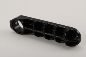
The examination and models show that for most trim applications, the plan of the ejector framework is driven more by the yield stresses applied on the plastic embellishment as opposed to by the compressive weights on the pin. Notwithstanding, compressive pressure can cause locking in long, thin individuals, for example, ejector pins. Consequently, further investigation of the compressive anxieties is significant, and will be accordingly used to dodge pin clasping. This article is from http://www.chinainjectionmold.com
UC Cycle

The UC cycle approach, with its exceptional capacity to develop parts in a”cold” strong state design, holds extraordinary guarantee, particularly if the base metal ability can be extended to satisfy new market needs. The framework inalienably fits delivering metal parts with fantastic dimensional control and material properties because of a few interesting cycle attributes:

  • Solid-state creation There is no fluid to metal change in the UC cycle, along these lines dimensional exactness effectively meets designing necessities that are out of sight go after numerous other direct metal cycles. This permits fast creation and ongoing component age. Also, the chilly statement measure fits the consolidation of help materials that must be utilized in temperature goes well underneath the liquefying purpose of the material with the goal that hardening happens, in this manner utilizing the additional solidness and unbending nature for complex part fabricating.
  • Integrated three-pivot processing focus UC is a mixture added substance metal cycle in that the testimony stages are intermittently trailed by exact material evacuation stages utilizing customary CNC innovation. This is made conceivable in huge part to the point noted previously.
  • Ultrasonic bond quality-The UC cycle uses ultrasonic joining of dainty foil layers for a strong state measure. The resultant interlaminar bond quality is that of a metal lurgical bond and is portrayed by fine grain structures not at all like the coarse recast layers normal inside different cycles.
  • Multimaterial covers UC empowers holding and joining of different materials, for example, glass metals, Al-Ti, Cu-Al and so forth Table 6.3 shows the huge number of thermodynamically viable materials blends under UC conditions. These materials can possibly be utilized in this UC cycle.

The ultrasonic welding parts of the Formation machine are depicted in this segment. As appeared in Figure 6.76, the sonotrode is a finished chamber that cinches the added substance layer or foil (or tape) to the substrate and vibrates at ultrasonic frequencies and micron-scale amplitudes. In the ideal case, the sonotrode and new layer move together and the vibration energy is moved from the sonotrode-tape interface (STI zone) into the tape-substrate interface.

This tape- – substrate interface disfigured district, called distortion influenced zone. (DAZ), encounters plastic disfigurement that breaks and scatters surface oxides and foreign substances, accordingly bringing molecularly clean metal surfaces into contact and making a genuine metallurgical bond. Figure 6.77 shows the microstructure of the DAZ disfigured district.

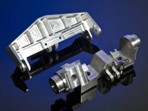
Solidica utilized RPCAM programming to consolidate the standard 3D CAD model into the affidavit and processing methodology inside the CNC machine code for part fabricating. A case of an injection shape created as such is appeared in china plastic rapid prototyping suppliers.

These consolidated credits of the framework empower such plans as a completely incorporated conformal cooling framework without the utilization of jolts and sealants, and different parts. This altogether decreases costs in materials, work, and time to showcase. Another model is appeared in precision cnc prototype manufacturers.

The UC cycle can be further illustrated in sheet metal rapid prototyping manufacturers china shows two pieces of materials to be welded. Figure 6.80b shows the materials are welded utilizing a moving sonotrode. Figure 6.80c shows the machining activity after the materials are welded. Figure 6.80d shows the roundabout shape subsequent to machining. Figure 6 .80e shows the welded part with the third strip machined to a space in the middle. Figure 6.80f shows the part with the fourth strip. Along these lines, UC can be utilized to create some interior pits. By utilizing ultrasonic welding and machining, complex calculations and ideal plans would now be able to be acknowledged where ordinary machine apparatus cycles would not have the option to deliver such highlights.

In synopsis, the upsides of the UC cycle incorporate the accompanying:

  • Directly manufacture metal items from modest foil feedstock
  • Incorporate complex interior calculations, depressions, and channels
  • Functionally reviewed composite assembling capacities
  • High highlight to-include exactness (+0.002 to around +0.005 in.)
  • High fa brication speed
  • Low measure heat
  • Low cost contrasted with utilizing high fuel source to create metals
  • Reduced optional machining activities
  • Stop and restart to work whenever

The uses of the UC cycle incorporate venture projecting, vacuum shaping, blow forming, infusion forming, and direct aluminum model parts. Notwithstanding framing metallurgical securities, plastic stream created by ultrasonic excitation is sufficiently able to typify an assortment of strengthening materials. Fiber composites can be collected by setting the filaments between layers of metal foils. High quality strands, for example, silicon carbide and boron can be installed to make firm boards, while 2D lattices can advance isotropy. Shape memory composites like nitinol can be incorporated with an aluminum lattice to make smart portable parts. Sensors, for example, thermocouples or strain gages can likewise be embedded. This cycle is a decent mechanized choice to paste, screws, or snap-fit plans, yet it is generally utilized in applications for little pieces, for example, watches, tapes, toys, and clinical devices by the micro machining machined parts manufacturers china. The uses of ultrasonic metal welding are quickly growing, and it has just been demonstrated relevant to the car aluminum case, for example, the all aluminum Jaguar.

This article is from http://www.chinainjectionmold.com/