Split Cavity

One split hole form configuration is appeared in china high precision mold manufacturer for the trim of bowling pins. The shape incorporates a top brace plate 14, a cavity retainer plate 16, and a help plate 12, among others. The split depression is framed by two moving pit embeds 23 and 24 that mate with the tapered bore 21 in the cavity retainer plate 16 when the form is shut. Four lengthened point pins 30 are secured in the top clip plate and stretch out through the cavity embeds 23 and 24. Every pit embed is attached to two gibs 28 that can cross in slideways 26.

At the point when the shape opens, the help plate 12 is moved away from the cavity retainer plate 16. Since the point pins 30 are fixed and slanted comparative with the form opening bearing, the pit embeds 23 and 24 are compelled to move away from one another through a cam activity. At last, an adequate leeway is delivered between the shaped section 66 and the cavity side dividers 44 with the goal that the formed item might be taken out.
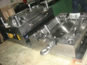
There are a couple of fascinating things to note with respect to this specific split pit shape plan. To start with, there is a lot of shape cheek gave in the hole retainer plate 16. The thickness of the cheek is needed to stay away from unreasonable shear pressure and diversion of the depression side dividers 44. It is seen that the thickness of the cheek is around equivalent to the profundity of the shape depression, as proposed by the investigation of china precision injection plastic parts factory. Second, wear can be an issue in this form configuration because of the enormous mass of the supplements, the length of movement, and the high number of trim cycles. Hence, the gibs should be determined to incorporate lubricity and be effortlessly supplanted when important. Likewise, wear plates should be joined between the help plate 12 and the cavity embeds 23 and 24. Third, interior cooling of the center is given using a huge bubbler 75 with coolant delta 74 and source 76.

Split depression molds have been intended for a long while, and this plan was not chosen exclusively because of its consolidation of a split hole plan. Another fascinating component of the plan is the forward incitation of the center pin 50 during the filling and pressing stages to give infusion pressure forming. This activation is expected to make up for the exceptionally high volumetric shrinkage during the hardening of the thick side dividers 54 of the formed part. Accordingly, the shape configuration incorporates a heading 46 that bolsters the shoulder 65 of the center pin. Since the shaped section 66 will in general therapist onto the center pin 50, the center pin should be withdrawn after the form is opened as appeared in china injection mold factory to deliver the shaped part.

The distance across of financially accessible folding centers goes from 13 to 90 mm, with a breakdown of around 6 % of the center measurement. While their breakdown isn’t close to as much as the plan of precision molds factory, these standard segments uphold completely programmed trim of little highlights, for example, inner strings for shaped terminations. This article is from http://www.chinainjectionmold.com/
Mold Wall

The investigations and plans introduced for mold cooling are sufficient for most inject molding applications in oem/odm automotives mould factory. In any case, there are a few applications wherein the utilization of customary cooling plans is unsatisfactory. Regularly, the improvement of a set skin happens when the hot polymer dissolve contacts the virus form divider. In some trim applications, the solifed skin may prompt untimely freeze off of the liquefy in the pit, unnecessary birefringence in the formed part, or insufficient degrees of sparkle or surface replication. In different applications in china precision injection plastic parts factory, mold divider temperature vacillations over the outside of the form hole may prompt an absence of dimensional control. In that capacity, some trim applications including focal points, plane cockpit overhangs, optical capacity media, and fiber fortified materials may try to improve the nature of the moldings through unique control of the mold divider temperature. A few distinct systems are next examined.

One way to deal with controlling the form divider temperature is to utilize at least one lots of cooling channels to effectively warmth and afterward effectively cool the mold. One such mold configuration is appeared in china high precision mold manufacturer; this was created to give tight resiliences when forming profoundly delicate plastic materials or exceptionally slim walled moldings. In this beat cooling plan, a mold hole 7 is framed by a hole embed 10 and a center supplement 9. The center addition is intentionally intended to be as thin as could be expected under the circumstances, and encompasses an inside center 12 to give a channel 14 to course for temperature controlled liquids. The cavity embed 10 is correspondingly intended to mate with the cavity plate 28 and the external supplement 29 to frame channels 24 and 25.

In activity, two liquids are independently temperature controlled with a warming gadget 35 and a cooling gadget 34; two separate liquids are prescribed to diminish the expense and time related with consecutively warming and cooling a solitary liquid.

Preceding the infusion of the polymer soften, the control valves 36 and 37 will guide the warmed liquid to the delta 18 and through the mold center by means of channels 14 and 15 preceding returning through the outlet 16; a comparative warming circuit is framed for the form hole through components 26, 22, 25, and 27. When the additions 9 and 10 are at a temperature over the point of solidification of the plastic soften, the plastic liquefy is injected into the depression 7. The control valves would then be able to be impelled to coordinate the cooling fl1uids from the cooling gadget 34 through similar channels recently utilized by china injection mold factory for warming.

The achievement of this mold configuration is profoundly reliant on limiting the mass of the form steel and coolant needed to frame and cool the dividers of the mold hole. It is plainly attractive to limit the thickness of the form embeds, the length of the cooling channels and lines, and the warmth move to nearby mold parts. In this plan, air holes 20, 29, and 38 are utilized to lessen the measure of warmth move thus improve the warm effectiveness and dynamic execution of the mold; protecting sheets (not numbered) are additionally given neighboring the top and back cinch plate to limit heat move to the platens. Shockingly, the size of the pit and the basic prerequisites on the form parts requires the utilization of genuinely huge mold segments that should be warmed and therefore cooled. The dynamic warm reaction is restricted.

This article is from http://www.chinainjectionmold.com