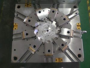
For china high-precision mould suppliers, the expression “parting line” alludes to the area at which the pit embed, the center addition, and the plastic trim meet. Since the center and depression embed meet at this area, any huge avoidance of the cavity embed away from the center supplement will bring about a hole into which the plastic will stream and structure a dainty film of plastic known as “streak.” Imperfections in the center and cavity embeds at this area, for example because of wear or inappropriate dealing with, will likewise make holes into which the plastic will stream. Indeed, even with new and all around made molds, the area of the splitting line as a rule brings about a slight “witness line” along its length.
Therefore, the splitting line ought to be situated along a base edge of the part, or some other non-visual, nonfunctional edge. Think about the past cup. Setting the splitting line extremely near the lip as shown by the ran line in the left drawing would bring about an observer line and conceivable glimmer that may make the molded cup unusable. A superior area for the splitting line is at the base of the edge as demonstrated, relating to the splitting line.
During injection moulding services china, for the PC bezel, the splitting line will be situated around the base edge of the part. It is seen that, in contrast to the cup, the splitting line for the bezel isn’t in a solitary plane. Or maybe, the splitting line follows the profile of the highlights as an afterthought dividers. This separating line is needed to fit the center addition, which hollows out the mold cavity to frame the openings required for the different connectors. As will be found in the following area, this mind boggling separating line mold will cause a more perplexing splitting plane.
When the splitting line is recognized, the splitting plane is extended outwards from the part to isolate the center supplement from the hole embed. The pit addition will mold the external and top surfaces of the part, while the center supplement will frame the edge and internal surfaces. For the PC bezel, the splitting line can be transmitted outward to frame the splitting surface. It tends to be seen that the entirety of the out-of-plane highlights along the splitting line n0w become complex surfaces on the splitting plane.
These surfaces present two huge issues during mold activity. To begin with, any misalignment between the sharp highlights on center and depression additions will cause wear between the sliding surfaces if not an inside and out effect between the main edge of the center and the mating pit surface. Second, the brace weight applied on the center and depression additions can make the surfaces lock along with outrageous power, causing exorbitant pressure and potential mold twisting during mold activity of china injection design service.

To evade inordinate pressure, interlocking highlights on the splitting plane ought to be slanted at any rate five degrees comparative with the mold opening course. The splitting surface is presently regularly made by means of three-dimensional PC supported plan (“3D CAD”) utilizing lobbed surfaces. Each hurled surface mixes a bended element along the splitting line to a line of comparing width on the splitting plane. The outcome is a surface with the required profile at the splitting line and the important draft down to the splitting plane. The hurled surfaces are then weave along with the splitting plane to give a splitting surface, as appeared for the bezel. These surfaces might be legitimately machined utilizing PC mathematically controlled (CNC) machining 0r by means of plunge electrical release machining (EDM) utilizing at least one anodes that were CNC machined.
This article is from http://www.chinainjectionmold.com/.