There are numerous applications for a filling examination, including cost decrease, measure enhancement, and quality upgrades in oem/odm industrial injection mold factory. While the accompanying models give a wide exhibit of run of the mill applications, the mold architect ought to alter or additionally build up these examinations as per the particular needs of the embellishment application.
Mold designers of design for injection molding china ought to check that the mold can be filled given the cavity calculation and the material properties. In any case, the filling examinations require the preparing conditions, including the soften temperature and either the straight speed or volumetric stream pace of the dissolve. It is suggested that mold creators expect a dissolve temperature in the liquefy temperature go suggested by the material provider, since this furnishes the disintegrate with some opportunity to alter temperatures up or down to address shaping issues or decrease process duration.
The genuine dissolve stream rate isn’t known until after the mold is made and authorized. The greatest stream rate is regularly limited by the most extreme slam speed of the embellishment machine or trim imperfections brought about by high stream rates, for example, streak, flying, or consume marks. The base stream rate is regularly limited by the untimely cementing of the liquefy in the mold hole, which brings about a short shot.
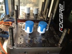
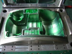
| two shots molds made in china |
Common straight stream speeds of the soften through the mold extend from0.01 to 1 m/s relying upon the particulars of the embellishment application. Slim divider applications will by and large have higher direct stream speeds on the grounds that
■they require a quicker infusion to dodge untimely cementing and
■their slimness accommodates quicker direct speeds given a similar volumetric stream rate from a trim machine.
Soften stream rates might be assessed by figuring the volume of the mold holes and sprinters and partitioning by the assessed filling time. This methodology functions admirably for those experts with experience yet may not function admirably for new embellishment applications having totally different calculations or material properties. On the other hand, extra examination can prompt a suggested stream rate that adjusts the measure of shear warming with the warmth misfortune from the dissolve to the mold. This outcome ought to give not just a sensible gauge of the dissolve stream rate, yet additionally a more precise examination since it will in general produce a unimold soften temperature as the liquefy fills the mold.
The determination of the liquefy speed is given in Appendix F. For a Newtonian material, the suggested speed is the place Tmelt and Twall are the soften and shape divider temperature, h is the warm conductivity of the plastic liquefy, and μ is the Newtonian thickness. Since the thickness is an element of the shear rate and speed, it is important to recompute the shear rate and consistency until the speed combines.
As suggested by china automatives injection overmould manufacturers, the suggested speed will change with the liquefy temperature, the mold temperature, the warm conductivity of the soften, and the dissolve thickness. Higher temperature contrasts between the dissolve and divider temperatures, just as higher warm conductivity of the polymer soften, require quicker liquefy speeds to keep up a unimold soften front temperature. Lower thickness materials require a higher soften speed to create the shear warming expected to dodge over the top warmth misfortune to the liquefy.
While the liquefy speed doesn’t seem to fluctuate with divider thickness, the impact of divider thickness is considered through the incorporation of the consistency, which is a component of the shear rate. As the divider thickness diminishes, the expanding shear rate decreases the consistency, which in this way requires higher liquefy speeds to abstain from cooling the soften. True to mold, higher soften speeds are required as the divider thickness diminishes. Figure 5.11 plots the suggested soften speed for ABS as an element of dissolve temperature and divider thickness utilizing the investigation. It is seen that the soften speed can differ from about 0.4 m/s for a trim application with a divider thickness of 3 mm and a liquefy temperature of 218°C to about 1.6 m/s for an embellishment application with a divider thickness of 0.8 mm and a dissolve temperature of 260°C .
While there is a huge range in the suggested soften speed as a component of the embellishment application, perceive that the specific liquefy speed and stream rate that will really happen during the trim cycle is obscure. The target ought to be to give a sensible gauge of the liquefy speed and occupying time and structure the shape to work under a wide assortment of conditions. While the previous investigation may appear to be pointlessly unpredictable contrasted with basically accepting a filling time dependent on experience, the examination is objective and gives a quantitative outcome that gives bits of knowledge to the plan and utilization of injection molds.
This article is from http://www.chinainjectionmold.com/